Frequently Asked Questions: Van Veen Triple Loop Antenna
What is a Van Veen Triple Loop Antenna and why is it used for lighting equipment testing?
The Van Veen Triple Loop Antenna — also called a Large Loop Antenna System (LAS) — is a three-axis measurement system consisting of three mutually perpendicular 2-meter loop antennas arranged around the Equipment Under Test (EUT). The geometry was developed at Philips Research Laboratories by Van Veen and Bergervoet to address the challenge of consistently measuring radiated magnetic disturbances from large, free-standing lighting products. The three orthogonal loops simultaneously capture the X, Y, and Z vector components of magnetic field emissions, so the EUT does not need to be physically rotated during testing. The Van Veen/Bergervoet principle was codified in CISPR 16-1-4 Annex C and is now the required measurement method for lighting equipment under CISPR 15 (EN 55015).
What is CISPR 15 / EN 55015 and which products require this testing?
CISPR 15 (identical to EN 55015) specifies the limits and methods of measurement of radio disturbance characteristics of electrical lighting and similar equipment. Compliance with CISPR 15 is required for CE marking in Europe and is widely referenced globally (as AS/NZS CISPR 15 in Australia/New Zealand, GB 17743 in China, and related national standards elsewhere). Products subject to CISPR 15 include LED drivers, LED lamps and fixtures, fluorescent ballasts (electronic and magnetic), HID ballasts, CFL integrated lamps, smart lighting (Zigbee, Matter, Bluetooth Mesh, DALI-controlled), TRIAC and 0–10V dimmers, DMX lighting controllers, LED signage and channel-letter lighting, horticultural grow lights, UV-C disinfection lamps, and medical/dental surgical lighting — essentially any product whose primary function is generating artificial light.
What does the ALT-930-2M system include?
The ALT-930-2M is a complete three-axis Van Veen loop antenna system. It consists of three 2-meter-diameter loops arranged in mutually perpendicular planes, each constructed from high-quality RG 223/U coaxial cable housed inside flexible 1-inch PEX pipe for mechanical stability. Each loop connects to its own current-to-voltage transducer, and the three transducer outputs feed into the RAS-930 coaxial switch, which selects one loop at a time for connection to the EMI receiver while terminating the other two loops in 50 Ω. The entire assembly mounts on a non-metallic fiber-glass/plastic support structure with swivel casters, so the antenna rolls between lab positions without disassembly. The optional RLI-100 Remote Interface enables fiber-optic remote control of the switch from the control room, and the optional ALT-930-CKIT provides the Balun-Dipole antenna and 10-meter coaxial cable required for in-lab periodic calibration verification.
Why are three mutually perpendicular loops required?
A single loop antenna responds only to the magnetic-field component perpendicular to its plane. Since the orientation of a lighting product’s emissions vector is unknown in advance — and because the EUT itself may be physically awkward to rotate (ceiling fixtures, large signage, mounted grow lights, etc.) — the only reliable way to capture the worst-case H-field is to measure along all three spatial axes. The Van Veen geometry does this by surrounding the EUT with three 2-meter loops in orthogonal planes (X, Y, Z). Each loop sees one vector component of the field; the CISPR 15 compliance decision is based on the worst-case reading across all three axes at each frequency. This approach is faster and more reproducible than physically rotating the EUT, which can be impossible with large or wired products.
What frequency range does the ALT-930-2M cover, and why that range?
The ALT-930-2M covers the full 9 kHz to 30 MHz band — the complete frequency range specified by CISPR 15 for radiated magnetic disturbance measurement of lighting equipment. At these frequencies, the dominant coupling mechanism for lighting-product emissions is through the magnetic (H-field) component, which is why CISPR 15 requires loop-antenna (H-field) measurement rather than the E-field dipole/biconical/log-periodic methods used for higher frequencies. The lower limit of 9 kHz captures switching-frequency fundamentals of modern LED drivers and fluorescent ballasts; the 30 MHz upper limit is the traditional boundary between “radiated” (far-field antenna) and “conducted” (mains-port) EMC measurement methodologies. Above 30 MHz, lighting-equipment measurement transitions to conventional E-field antennas and CISPR 32 limits.
How does the Large Loop Antenna System (LAS) principle of operation work?
Each 2-meter loop functions as a large shielded current-sensing transformer primary. Magnetic fields produced by the EUT at the center of the loops pass through each loop, inducing a current in the loop conductor proportional to the rate of change of magnetic flux (Faraday’s law: V = −N · A · dB/dt). The induced current drives a current-to-voltage transducer at the loop terminals, which converts it to a calibrated voltage proportional to the magnetic field. Because the three loops are mutually perpendicular and their responses are matched to the “ideal loop curves” defined in CISPR 16-1-4, they independently capture the three vector components of any magnetic field. The 2-meter diameter is large enough to accommodate typical lighting products inside while keeping the measurement relatively insensitive to the exact EUT position within the central volume.
What is the RAS-930 Remote Antenna Switch and why is it integrated into the system?
The RAS-930 is a three-position coaxial switch that connects one loop’s current-to-voltage transducer output to the EMI receiver while terminating the other two loops into 50 Ω. This is essential because: (1) a typical EMI receiver has only one RF input, so the operator needs a way to select X, Y, or Z programmatically; (2) un-terminated loops act as resonant reflectors that distort measurements on the active loop — the two inactive loops must be properly loaded during measurement; and (3) manual cable-swapping between axes is slow, error-prone, and introduces connector wear at every transition. The RAS-930 automates this correctly per the CISPR 15 method. Control is available locally via front-panel or remotely via fiber-optic interface using the optional RLI-100 Remote Interface — the fiber link is critical because any metallic cable entering or exiting the loop volume would itself couple with the magnetic field and distort the measurement.
How is the ALT-930-2M calibrated and what traceability is provided?
Each ALT-930-2M is individually calibrated per the requirements of CISPR 16-1-4. The calibration process uses a small Balun-Dipole reference antenna placed at the geometric center of the loop structure and driven with a known RF current; the induced current in each of the three loops is measured and compared against the theoretical ‘ideal loop curve’ defined in CISPR 16-1-4 and CISPR 15 to verify each loop’s response is within tolerance. Every ALT-930-2M ships with individual calibration data and a certificate, traceable to NIST. The optional ALT-930-CKIT includes the Balun-Dipole antenna, its mounting structure, and a 10-meter RG 223/U cable for in-lab periodic calibration verification between annual recalibrations. ISO 17025 accredited calibration is available upon request for labs whose accreditation bodies require an externally audited certificate.
ALT-930-2M Van Veen Triple Loop Antenna System (CISPR 15 Lighting)
⭘ ALT-930-2M: 9 kHz – 30 MHz Three-Axis LAS | CISPR 15 / EN 55015
The ALT-930-2M Triple Loop Antenna is designed based on the Loop Antenna System (LAS) described in Annex C of CISPR 16-1-4. The antenna consists of three mutually perpendicular large loop antennas having diameters of two (2) meters. The loops are constructed from high quality RG 223/U coaxial cable, inside flexible 1” PEX pipe. The three (3) loops connect to three (3) current to voltage transducers, the outputs of which connect to three respective inputs on a coaxial switch. The switch is used to select which loop connects to the measuring instrument, while terminating the other two loops into 50 ohms. The switch can be controlled locally or remotely via fiber optic interface with the optional RLI-100 Remote Interface. The antenna assembly is supported by a fiber glass/plastic mounting structure employing swivel casters, enabling the antenna to easily be moved without disassembly.
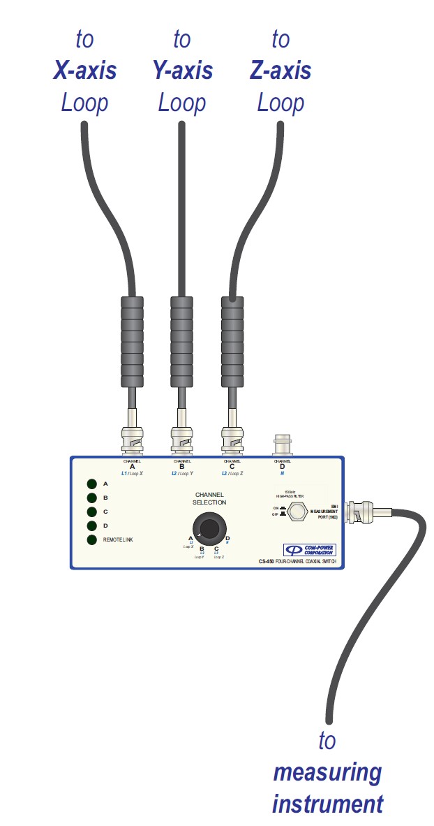
Figure 1: ALT-930-2M three-axis loop structure.
Three mutually perpendicular 2-meter loops made of RG 223/U coaxial cable inside 1″ PEX pipe, mounted on a non-metallic fiberglass/plastic support frame with swivel casters. The Equipment Under Test (EUT) is placed in the approximate center of the loop volume; each loop independently captures one vector component (X, Y, or Z) of the radiated magnetic-field disturbance. The rolling support lets the complete assembly be repositioned between lab bays without disassembly.
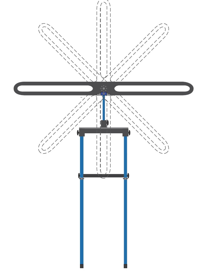
Figure 2: Current-to-voltage transducers and RAS-930 switch.
Each loop connects to its own current-to-voltage transducer; the three transducer outputs feed the RAS-930 coaxial switch. The switch routes one loop’s signal to the EMI receiver while terminating the other two loops in 50 Ω to prevent resonant reflections that would distort the active-loop measurement. Switch control is available locally or remotely via fiber optic using the optional RLI-100 Remote Interface.
The primary application for this antenna is the measurement of radiated magnetic fields (or radiated electromagnetic disturbances) generated by various types of electrical lighting and similar equipment while located in the approximate center of the Triple Loop Antenna structure, as per the requirements of CISPR 15 (EN 55015).
The ALT-930-2M is individually calibrated in compliance with the relevant requirements of CISPR 16-1-4, and is provided with calibration data and certificate, traceable to NIST. Recognized ISO 17025 accredited calibration is also available upon request. The optional ALT-930-CKIT Calibration Kit includes the Balun-Dipole antenna described in CISPR 16-1-4, as well as its mounting structure and 10-meter RG 223/U coaxial cable for connection to the signal source (Please refer to detailed datasheet for the detailed specifications).
Frequency Range:
- 9 kHz – 30 MHz
- CISPR 15 / EN 55015 compliant
- CISPR 16-1-4 Annex C geometry
Loop Construction:
- Three 2-meter diameter loops (X, Y, Z)
- Mutually perpendicular geometry
- RG 223/U coax in 1″ PEX pipe
- Electrostatically shielded
System & Mechanical:
- Three current-to-voltage transducers
- RAS-930 coaxial switch (X/Y/Z select)
- Non-metallic fiberglass/plastic frame
- Swivel casters for easy repositioning
- Optional RLI-100 fiber-optic remote
Calibration & Options:
- Individual cal per CISPR 16-1-4
- NIST traceable
- ISO 17025 available on request
- Optional ALT-930-CKIT cal kit
- (Balun-Dipole + mounting + 10 m cable)
Key Applications:
- CISPR 15 / EN 55015 Lighting Equipment Compliance: Primary three-axis H-field measurement system for certifying LED drivers, LED lamps, fluorescent and HID ballasts, CFL, smart lighting, dimmers, signage, horticultural lights, and UV equipment for CE marking and international compliance.
- Accredited Compliance Testing: ISO 17025 labs performing third-party lighting EMC certification for manufacturers, distributors, and regulatory bodies.
- Pre-Compliance & Design Verification: In-house screening by lighting OEMs before formal accredited testing — identifies and corrects switching-harmonic emissions issues early in the design cycle.
- Product Surveillance & Market Sampling: Periodic re-verification of production units to confirm ongoing compliance after manufacturing variations, supplier changes, or firmware updates.
- Research & Development: Characterizing new LED driver topologies, power-factor-correction stages, dimming technologies, and smart-lighting radios for magnetic-field emissions behavior.
- Global Compliance Coverage: CISPR 15 (international), EN 55015 (European Union), AS/NZS CISPR 15 (Australia/NZ), GB 17743 (China), VCCI (Japan reference), and other national standards harmonized with CISPR 15.
View ALT-930-2M Details →
Why the Van Veen/Bergervoet Geometry?
The Van Veen/Bergervoet triple-loop geometry originated at Philips Research Laboratories during the 1990s, developed to solve a long-standing problem in lighting EMC: measuring large, free-standing lamp assemblies with consistent, reproducible results across different test laboratories. Before the Van Veen method, CISPR 15 lighting emissions were measured with a single loop and manual EUT rotation — an approach that was slow, operator-dependent, and difficult to reproduce across labs.
Van Veen and Bergervoet showed that a specific three-loop geometry — three mutually perpendicular loops of specified diameter, with defined transducer characteristics and termination — produces a measurement system whose response is defined purely by geometry, not by the specific mechanical frame or lab setup. Any lighting product placed at the loop center produces the same measurement regardless of which lab performs the test, provided the lab’s LAS conforms to the same geometric and electrical specifications.
The Ideal Loop Curve
CISPR 16-1-4 Annex C defines the ‘ideal loop curve’ — the theoretical response of a perfect Van Veen loop to a reference magnetic source at the center. A compliant LAS must have each of its three loops’ responses matched to this ideal curve within tolerance. The ALT-930-2M’s individual calibration verifies each loop against this ideal curve, using the Balun-Dipole reference source from the ALT-930-CKIT placed at the geometric center. This is the calibration chain that makes CISPR 15 results comparable across any accredited lab worldwide.

