
AL-RE101 Passive Loop Antenna for MIL-STD-461 RE101 Testing
- The AL-RE101 is a passive receiving loop antenna for MIL-STD-461 RE101 magnetic field emissions testing, covering 30 Hz to 100 kHz (usable 10 Hz to 1 MHz).
- Built to MIL-STD-461 geometry: 13.3 cm, 36-turn coil of 7-strand 41 AWG Litz wire in a powder-coated electrostatic shield. Litz construction reduces AC resistance for better sensitivity. BNC female output to 50Ω.
- Nylon base over a plexi-glass plate that protrudes forward to automatically fix the loop center exactly 7 cm from the EUT when placed flush — no ruler, no fixture, no distance error.
- MIL-STD-461 RE101 qualification for Navy, Army, and aerospace platforms where low-frequency H-fields can interfere with compasses, magnetometers, and sensitive avionics.
- Pre-compliance H-field debug — scan transformers, motors, solenoids, and switching converters to find problem frequencies before formal RE101 testing. Compact 0.84 lbs / 7.48″ × 6″ × 3.8″ for easy handling.
- Cable and sub-assembly scanning — locate magnetic emissions along harnesses, or characterize individual power supplies, converters, and motor drives before system integration.
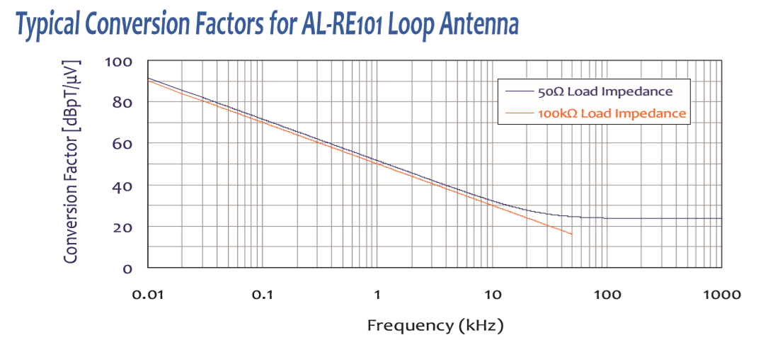
- Calibration supplied for both 50Ω and 100 kΩ load impedances — works with EMI receivers, spectrum analyzers, and high-impedance instruments like oscilloscopes. 10Ω / 340 µH wire characteristics.
- Individually calibrated per SAE ARP-958 and MIL-STD-461 with NIST traceability. ISO 17025 calibration available on request. Three-year warranty.
Features
- ▸ Designed specifically for MIL-STD-461 RE101 testing — receiving loop purpose-built to measure magnetic field emissions from equipment and subsystem enclosures (including electrical cable interfaces) over 30 Hz to 100 kHz.
- ▸ Built-in 7 cm spacing plate enforces standard geometry — the plexi-glass plate mounted to the nylon base protrudes outward from the front of the antenna, automatically fixing the loop center exactly 7 cm from the EUT surface when placed flush. Eliminates ruler measurements and distance error from every measurement.
- ▸ Frequency range 30 Hz to 100 kHz (usable 10 Hz to 1 MHz) — specified range covers the entire MIL-STD-461 RE101 band; usable range extends an additional decade above and below for diagnostic and pre-compliance work.
- ▸ 13.3 cm diameter, 36-turn, Litz-wire coil — coil construction is built to MIL-STD-461 prescribed geometry, ensuring measurement results are reproducible across different test laboratories worldwide.
- ▸ 7-strand 41 AWG Litz wire reduces AC resistance — multi-strand Litz construction mitigates skin effect and proximity effect at audio and low-RF frequencies, lowering thermal noise and improving sensitivity for the low-level magnetic field measurements typical of RE101.
- ▸ Powder-coated electrostatic shield with deliberate gap — grounded shield blocks E-field coupling so the loop responds only to magnetic fields; the shield gap is essential to prevent the shield from acting as a short-circuited turn that would block magnetic flux. Powder coating adds mechanical durability for daily field test use.
- ▸ Plane of loop oriented per RE101 requirements — positioned with loop plane parallel to the EUT face and parallel to the axis of connectors being measured, exactly as specified in the standard.
- ▸ High-quality female BNC output connector — standard 50Ω coaxial interface for direct connection to EMI receivers, spectrum analyzers, or low-noise preamplifiers.
- ▸ Compact and lightweight — just 0.84 lbs (0.38 kg) and 7.48″ H × 6″ W × 3.8″ L, easy to position by hand against EUT enclosures and cable interfaces during scanning.
- ▸ Durable nylon base over plexi-glass plate — rugged construction designed for daily test-lab use; non-conductive base materials prevent measurement disturbance from the antenna structure itself.
- ▸ Conversion factor data for 50Ω and 100 kΩ loads — calibration covers both the standard 50Ω receiver input and high-impedance instrument inputs (e.g., oscilloscopes), enabling accurate field strength calculation in either configuration.
- ▸ Individually calibrated per SAE ARP-958 and MIL-STD-461 — calibration is performed using NIST-traceable equipment; calibration data and certificate ship with each unit; ISO 17025 accredited calibration available on request.
- ▸ Three-year standard warranty — backed by manufacturer support.
Specifications
| Model | AL-RE101 |
|---|---|
| Antenna Type | Passive Receiving Loop Antenna (Magnetic Field) |
| Frequency Range | 30 Hz to 100 kHz (usable range: 10 Hz to 1 MHz) |
| Loop Diameter | 13.3 cm |
| Number of Turns | 36 turns |
| Wire Type | 7-strand, 41 AWG Litz wire |
| Loop Shielding | Electrostatic shield (powder coated) |
| Resistance of Wiring | 10 Ω (nominal) |
| Inductance of Wiring | 340 µH (nominal) |
| Maximum Input Current | N/A (receive only) |
| Connector | BNC (female) |
| EUT Spacing | 7 cm (built-in plexi-glass plate) |
| Conversion Factors | See typical conversion factor graph (50 Ω and 100 kΩ load impedance) |
| Applicable Standards | MIL-STD-461 RE101 |
| Calibration | Individually calibrated per SAE ARP-958 and MIL-STD-461, NIST traceable |
| Dimensions (H × W × L) | 7.48″ × 6″ × 3.8″ [19 × 15.35 × 9.7 cm] |
| Weight | 0.84 lbs [0.38 kg] |
| Warranty | Three-year standard warranty |
All values are typical, unless specified. All specifications are subject to change without notice.
🔍 Not Sure Which Antenna You Need?
Compare all Com-Power antenna models side-by-side with our interactive selection tool. Filter by frequency range, antenna category, application, polarization, and power handling to find your perfect match.
Compare All Antenna Models →AL-RE101 Passive Loop Antenna — Frequently Asked Questions
1. What is the Com-Power AL-RE101 and what is it primarily used for?
The AL-RE101 is a passive receiving loop antenna purpose-built for MIL-STD-461 RE101 radiated emissions (magnetic field) testing from 10 Hz to 100 kHz, with usable response down to 10 Hz and up to 1 MHz. It measures the magnetic (H-field) emissions radiated from equipment enclosures, electrical cable interfaces, and subsystem hardware to verify compliance with the RE101 limit curve. The antenna is also widely used for FCC Part 15 and Part 18 KDB low-frequency H-field measurements, magnetic field emissions debug on switching power supplies and motor drives, and site-survey work.
2. What are the AL-RE101’s key electrical and mechanical specifications?
Frequency: 30 Hz – 100 kHz (specified), usable 10 Hz – 1 MHz. Loop diameter: 13.3 cm. Turns: 36. Wire: 7-strand 41 AWG Litz wire. Shielding: electrostatic shield with deliberate gap, powder-coated for durability. Resistance: 10 Ω nominal. Inductance: 340 µH nominal. Connector: BNC female. Base: durable nylon mounted over a plexi-glass spacing plate that protrudes outward to enforce the MIL-STD-461-required 7 cm distance between loop center and EUT surface. Calibration: individual per SAE ARP-958 with NIST traceability; ISO 17025 available on request. 3-year warranty.
3. What is MIL-STD-461 RE101 and why does it require a specialized loop antenna?
RE101 is the MIL-STD-461 requirement for radiated emissions of magnetic fields from equipment and subsystem enclosures, including electrical cable interfaces, from 30 Hz to 100 kHz. Unlike E-field emissions tests that use biconical or log-periodic antennas, RE101 is measured with a magnetic loop antenna because the near-field of low-frequency sources is dominated by H-field. MIL-STD-461 prescribes exact loop geometry — 13.3 cm diameter, 36 turns, Litz wire construction, electrostatic shielding, 7 cm EUT spacing — because these parameters set the antenna factor and sensitivity that the standard’s limit curve assumes. Using any non-compliant loop would produce results that cannot be directly compared to the RE101 limit.
4. Which standards and agencies accept the AL-RE101?
• MIL-STD-461 (all revisions C through G) RE101 radiated emissions magnetic field
• U.S. Navy, Army, Air Force, Marine Corps platform qualification programs
• DoD contractor requirements for military electronic equipment
• FCC Part 15 Subpart B and Part 18 KDB low-frequency H-field measurement guidance
• NASA GEVS-SE and similar space-flight EMI specifications referencing RE101
• Pre-compliance debug against IEC 61000-6-3/4 and CISPR low-frequency magnetic emissions
• Automotive CISPR 25 related low-frequency magnetic field assessment
• ISO 17025 accredited laboratories using AL-RE101 for commercial and military programs
5. Why is the AL-RE101 a passive antenna rather than an active one?
Passive loops have no preamplifier, battery, or active electronics — just a wound coil feeding a receiver directly. For RE101 this is the correct architecture for four reasons: (1) Virtually unlimited dynamic range — no preamplifier to saturate under strong emissions during close-proximity scans; (2) No added noise — receiver noise floor dominates, and modern EMI receivers are extremely quiet at RE101 frequencies; (3) No battery maintenance — no power to check or replace during qualification campaigns; (4) Fully reproducible geometry — the Litz-wire coil, shield, and spacing plate are the entire signal path, so calibration stays stable over years. Active loops (like the AL-130R) are optimized for low-signal site surveys, not the strong near-field emissions that RE101 probes.
6. Why does the AL-RE101 include a built-in 7 cm plexi-glass spacing plate?
MIL-STD-461 RE101 requires the loop center to be positioned exactly 7 cm from the EUT face or connector being measured — this distance is baked into the limit curve and the standard’s antenna factor assumption. The AL-RE101’s plexi-glass base plate protrudes outward from the antenna front so that when the plate is placed flush against the EUT surface, the loop center sits at exactly 7 cm without any ruler, tape, or external fixture. This eliminates a major source of measurement uncertainty — distance errors of even 1 cm at close proximity produce multi-dB errors because near-field H-field falls off very steeply with distance.
7. Why is Litz wire used instead of solid copper in the AL-RE101?
Litz wire consists of many individually insulated thin strands woven so each strand occupies every position in the bundle equally. This construction mitigates two AC loss mechanisms at the 30 Hz – 100 kHz range: (1) Skin effect — RF current concentrates near the conductor surface, increasing effective resistance at higher frequency; (2) Proximity effect — adjacent turns in a wound coil push current to specific regions of each wire, further raising loss. The AL-RE101 uses 7-strand 41 AWG Litz wire (41 AWG is very fine — about 0.08 mm diameter per strand), which keeps AC resistance low across the full RE101 band. Lower resistance means lower thermal noise and better sensitivity for the receive loop.
8. What is the electrostatic shield, and why does it have a gap?
The electrostatic shield is a grounded conductive enclosure around the coil, powder-coated for mechanical protection. Its job is to block electric-field (E-field) coupling so the loop responds only to magnetic fields — essential for pure H-field measurement. The shield has a deliberate gap on one side — this is critical. A complete un-gapped shield would form a short-circuited one-turn loop that physically blocks the magnetic flux from reaching the coil inside. The gap breaks this unwanted shorted turn, so magnetic flux freely enters the shield to couple with the coil, while the shield still provides E-field rejection. This is a standard technique in all MIL-STD-461 loop antennas.
9. How does the AL-RE101 compare with other Com-Power loop antennas?
• vs. AL-RS101-SET (30 Hz–100 kHz, TX/RX pair): RS101-SET generates and calibrates magnetic fields for susceptibility (immunity) testing; AL-RE101 receives magnetic fields for emissions. Different test methods, often owned together
• vs. AL-130R (active loop, 9 kHz–30 MHz, CISPR): AL-130R is an active battery-powered loop for commercial CISPR H-field site surveys; AL-RE101 is the military-spec passive loop for MIL-STD-461 close-proximity measurements. Different standards, different architectures
• vs. AM-741R (active monopole, 9 kHz–30 MHz, E-field): AM-741R measures E-field; AL-RE101 measures H-field. Complementary, often used together in MIL-STD-461 full-range labs
• vs. ALT-930-2M (Van Veen triple loop, 9 kHz–30 MHz): ALT-930-2M is a 2-m three-axis CISPR 15 system for lighting equipment; AL-RE101 is a small 13.3-cm close-proximity loop for MIL-STD-461. Completely different applications
10. What real-world products and systems use AL-RE101 testing?
• Naval shipboard electronics — navigation systems, communications, combat systems, propulsion control (where low-frequency magnetic emissions could interfere with compasses, magnetometers, or magnetic anomaly detection)
• Military airborne systems — flight control computers, mission computers, display units, power distribution, avionics bays
• Army ground vehicles — tactical radios, weapons control, engine controllers, platform electronics
• Aerospace and space flight — satellite payloads, launch-vehicle avionics, deep-space instruments
• Crew-worn and dismounted electronics — soldier radios, helmet displays, body-worn computers
• Switching power supply debug — DC-DC converters, PFC stages, motor drives, inverters producing strong low-frequency magnetic emissions
• Transformers, solenoids, relays, contactors — characterizing stray magnetic emissions
• Cable and harness scanning — identifying localized H-field leakage points along routed cables
11. What receiver and cabling should I use with the AL-RE101?
• Receiver: any EMI receiver or spectrum analyzer covering 30 Hz to 100 kHz — most modern receivers extend to 9 kHz or lower, and specialty low-frequency front-ends go down to 10 Hz
• Detector settings per MIL-STD-461: peak and quasi-peak typically, with bandwidths per the standard’s Table (10 Hz below 1 kHz, 100 Hz from 1–10 kHz, 1 kHz from 10 kHz–100 kHz)
• Cable: 50 Ω coaxial with BNC male on the antenna end; keep the run short (< 2 m when possible) to minimize pickup, especially at higher frequencies
• Transient limiter: strongly recommended — strong low-frequency magnetic emissions can produce high-voltage transients at the receiver input. Com-Power offers compatible transient limiters
• Antenna factor: apply the individual AF vs. frequency data from the calibration certificate to convert dBµV readings to dBµA/m
12. How is the measurement actually performed per MIL-STD-461 RE101?
• Positioning: Place the AL-RE101 with its plexi-glass plate flush against the EUT face or electrical interface connector, orienting the plane of the loop parallel to the EUT face and parallel to the axis of the connector
• Scanning: Move the loop slowly across the EUT enclosure surface and along cable runs to find maximum-emissions locations; record the worst-case frequency and amplitude
• Orientation: Test each of the three orthogonal orientations at every scan position to capture any vector component of the H-field
• Distance control: The 7 cm built-in spacing is fixed; do not try to “get closer” — doing so invalidates the RE101 limit comparison
• Frequency sweep: Cover the full 30 Hz – 100 kHz band with the appropriate resolution bandwidth at each subrange
• Record: Document the highest reading at each frequency, the location on the EUT, and the loop orientation for traceability
13. Why is calibration critical and what does NIST-traceable mean?
Without accurate calibration, you cannot prove the EUT’s emissions were below or above the RE101 limit — the measurement is not admissible as compliance evidence. Every AL-RE101 is individually calibrated per SAE ARP-958 (the recognized method for magnetic loop antenna calibration) using NIST-traceable equipment. The calibration produces an antenna factor (AF) table in dB(1/m) vs. frequency — apply this to the receiver’s dBµV reading to get the H-field strength in dBµA/m. NIST traceability means Com-Power’s calibration standards are measured against standards that chain back to the U.S. National Institute of Standards and Technology — the legal basis for test report validity. ISO 17025 accredited calibration is available when your accrediting body requires it.
14. What are common measurement pitfalls with the AL-RE101 and how do I avoid them?
• Nearby metal objects — the loop is sensitive to any conductive surface nearby; keep test fixtures, cart frames, and personnel a reasonable distance from the antenna
• Ambient magnetic interference — shielded rooms don’t block low-frequency magnetic fields very well; take a baseline ambient scan with the EUT powered off to identify ambient lines from power transformers, flicker, and building infrastructure
• Orientation null — a loop has null response when its axis is perpendicular to the H-field direction; always measure all three orthogonal orientations
• Loose connector — verify BNC connector tightness; intermittent contact produces noise and false readings
• Incorrect AF application — make sure the calibration file matches the antenna serial number and is applied correctly in the receiver
• Saturation of receiver input — strong emissions close to the EUT can overload the receiver front end; use an appropriate attenuator or transient limiter
15. What are the AL-RE101’s key design advantages?
• Purpose-built for MIL-STD-461 RE101 — exact geometry matches the standard’s antenna factor assumption
• Built-in 7 cm plexi-glass spacing plate — enforces correct test geometry without external fixturing
• 13.3 cm loop, 36 turns, 7-strand 41 AWG Litz wire — optimized for the 30 Hz–100 kHz band
• Powder-coated electrostatic shield with gap — blocks E-field coupling without blocking magnetic flux
• 10 Ω / 340 µH nominal coil — well-matched characteristics for modern EMI receivers
• Passive (no preamplifier, no battery) — unlimited dynamic range, no saturation, no maintenance
• Usable 10 Hz – 1 MHz — extended range beyond the 30 Hz–100 kHz RE101 specification
• Individual SAE ARP-958 NIST-traceable calibration; ISO 17025 available
• BNC female output — universal interface to receivers and analyzers
• Durable nylon base + powder-coated shield — lab abuse tolerance
• 3-year standard warranty
16. When should engineers select the AL-RE101 over other Com-Power antennas?
Select the AL-RE101 when any of the following applies:
• You are performing MIL-STD-461 RE101 radiated emissions (magnetic field) qualification testing at any revision (C, D, E, F, G)
• Your program is Navy, Army, Air Force, Marine Corps, or space flight and requires RE101 compliance
• You are a defense contractor delivering equipment to DoD or prime contractors with MIL-STD-461 flowdown requirements
• You perform FCC Part 15/18 KDB low-frequency magnetic emissions measurements where H-field probing is required
• You need to debug strong magnetic emissions from switching converters, motor drives, transformers, or inductive sources during design
• You are scanning cables and harnesses for localized H-field leaks before or during formal testing
Choose the AL-RS101-SET if you need to generate magnetic fields for RS101 susceptibility testing. Choose the AL-130R for active-loop CISPR commercial H-field measurement from 9 kHz–30 MHz. Choose the ALT-930-2M for CISPR 15 lighting-equipment three-axis magnetic measurements.
Application Notes (PDF)
- AN-107 — What is Antenna Factor?
- AN-106 — Use of Antenna Factor for EMC Measurements
- Selecting the Right EMI Antenna
- Considerations when Selecting an Antenna for RF Immunity Testing
- EMC Antenna Calibration Requirements, Methodologies, and Best Practices
- NIST Antenna Calibration Services — Com-Power Capabilities and Traceability
- Com-Power EMC Antenna Product Line — Complete Specifications
Interactive Tools
- Antenna Finder Wizard
- Com-Power Antenna & Field Strength Calculator
- Com-Power EMC Compliance Limits Calculator
- Com-Power Cable Loss & Attenuation Calculator
Industry Applications
- Aerospace and Defense EMC Testing — MIL-STD-461 Requirements
- Automotive EMC Testing — ISO 11452 / CISPR 25
- Medical Device EMC Compliance — IEC 60601-1-2 Essentials
Blog Articles

Quote Request
Other EMC Test Equipment
- Absorbing Clamps
- Antenna Kits
- Antenna Masts - Automated and Manual
- Antennas
- Bulk Current Injection probes
- CDNs - Coupling Decoupling Network
- Comb Generators
- Conducted Immunity Test Systems
- Current Monitor Probes
- Current Probe Calibration Fixtures
- EM Clamps
- Feed Through Capacitor
- ISNs - Impedance Stabilization Network
- LISNs - Single Phase
- LISNs - TEMPEST
- LISNs - Three Phase
- Magnetic Field Generator
- Near Field Probes
- Power Amplifiers
- Pre-compliance Emissions Test Systems
- Preamplifiers
- Spectrum Analyzers
- Surge Generators
- System Controllers
- Transient Limiters
- Tripods For EMC
- Turntables