Frequently Asked Questions: Passive Loop Antennas
What is a passive loop antenna and how does it differ from an active loop antenna?
A passive loop antenna is a magnetic field (H-field) sensor consisting of a wound coil of wire — with no integrated preamplifier, no battery, and no active electronics. The voltage induced in the loop by a changing magnetic field is sent directly to the measurement receiver (for receive loops) or the loop is driven directly by a signal source to generate a magnetic field (for transmit loops). Because there are no active components, passive loops have no saturation limits, no battery maintenance, and extremely wide dynamic range — all advantages for the high-field levels encountered in MIL-STD-461 RS101 susceptibility testing. They are the preferred loop type for military testing because MIL-STD-461 prescribes specific passive loop geometries (diameter, turns, wire type) that ensure repeatable, cross-lab consistent results.
What are MIL-STD-461 RE101 and RS101 tests?
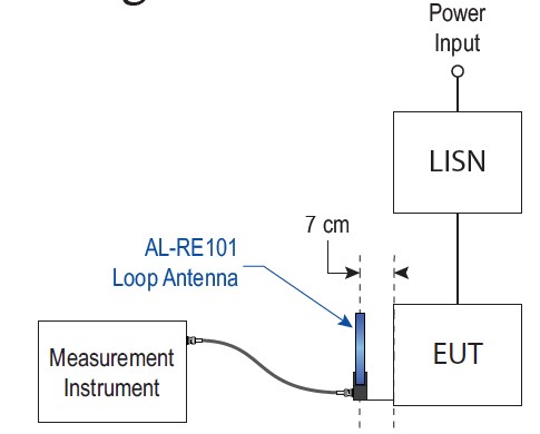
RE101 (Radiated Emissions, Magnetic Field) measures the magnetic field emissions radiated by military equipment and subsystem enclosures, including electrical cable interfaces, from 30 Hz to 100 kHz. The AL-RE101 receive loop is placed 7 cm from the EUT face to verify magnetic emissions do not exceed specified limits. RS101 (Radiated Susceptibility, Magnetic Field) exposes the EUT to a known magnetic field from 30 Hz to 100 kHz to verify it does not malfunction, degrade in performance, or deviate from specified indications. The AL-RS101-TX transmit loop generates the field; the AL-RS101-RX receive loop calibrates the field level. Both tests are required for military platforms where low-frequency magnetic coupling (from motors, power conversion equipment, and nearby cabling) is a concern.
Why are MIL-STD-461 loop antennas so specific in construction?
MIL-STD-461 prescribes exact loop geometries — diameter, number of turns, wire gauge, wire type, and shielding — because these parameters directly determine antenna factor, sensitivity, and field distribution. The AL-RE101 is specified as a 13.3 cm diameter, 36-turn, electrostatically shielded coil of 7-strand 41 AWG Litz wire. The AL-RS101-TX is specified as a 12 cm mean-diameter, 20-turn coil of 12 AWG enamel-insulated copper wire. These exact specifications ensure that emissions and susceptibility measurements are reproducible across different test laboratories worldwide — a critical requirement for military qualification programs where results are compared between contractors, government test facilities, and independent verification labs.
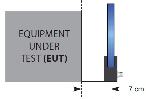
Why does the AL-RE101 include a fixed 7 cm spacing plate?
MIL-STD-461 RE101 requires the receive loop to be positioned exactly 7 cm from the EUT face or electrical interface connector being measured. The AL-RE101 incorporates this spacing into its mechanical design: the nylon base mounts over a plexi-glass plate that protrudes outward from the front of the antenna, placing the center of the loop exactly 7 cm from the EUT surface when the plate is placed flush against it. This eliminates distance-measurement errors and ensures every measurement is made at the standard-required geometry without additional fixturing or ruler measurements. The plane of the loop is oriented parallel to the EUT face and parallel to the axis of connectors being tested, also per RE101.
What does the AL-RS101-SET include and how is it used?
The AL-RS101-SET is a matched transmit/receive pair: the AL-RS101-TX transmit loop (12 cm mean diameter, 20-turn, 12 AWG enamel-insulated copper wire, 15 A continuous) generates the magnetic field to which the EUT is exposed, and the AL-RS101-RX receive loop (4 cm diameter, 51-turn, 7-strand 41 AWG Litz wire, electrostatically shielded) measures the actual field level generated during calibration. The set includes a fixed mounting arrangement that positions the RX loop at the standardized location on the TX loop, eliminating positioning error during test-level calibration. Per RS101, the TX loop is placed 5 cm from the EUT surface and driven with current to generate the required field strength; the RX loop verifies that field strength matches the test level specified in the RS101 limit curve.
How are Com-Power passive loop antennas calibrated?
Each AL-RE101, AL-RS101-TX, and AL-RS101-RX is individually calibrated using NIST traceable equipment per SAE ARP-958 and MIL-STD-461. The calibration data — antenna factor vs. frequency (for receive loops) or field-per-ampere vs. frequency (for transmit loops) — is supplied with each antenna along with a certificate of calibration. The data must be loaded into your EMI receiver, signal source, or test software so that measured voltage can be converted into magnetic field strength (dBµA/m or dBµT) or so that the required drive current can be calculated for a specified field level. ISO 17025 accredited calibration is available upon request for labs whose accreditation bodies require an externally accredited certificate. Annual recalibration is recommended to maintain measurement traceability.
Why use Litz wire in the AL-RE101 and AL-RS101-RX receive loops?
Both receive loops use 7-strand, 41 AWG Litz wire. Litz wire consists of multiple individually insulated strands woven together so that, over the length of the wire, each strand occupies every possible position in the bundle. This construction dramatically reduces AC resistance at the frequencies of interest (30 Hz to 100 kHz) by mitigating the skin effect and proximity effect that would otherwise force current to crowd into the outer surface of a solid conductor. Lower AC resistance means lower loss, lower thermal noise, and higher effective Q for the loop — all contributing to better sensitivity and measurement accuracy at the low magnetic field levels typical of RE101 emissions. The transmit loop (AL-RS101-TX) uses solid 12 AWG because it must carry up to 15 A continuous and high current capability outweighs AC resistance optimization.
What is the difference between an electrostatic shield and a Faraday cage around a loop?
The AL-RE101 and AL-RS101-RX receive loops are wound inside an electrostatic shield — a conductive enclosure with a deliberate gap. The shield is grounded and blocks electric field (E-field) coupling into the loop, ensuring the loop responds only to magnetic fields. This is critical for MIL-STD-461 RE101 because the measurement must isolate the magnetic component of EUT emissions from any electric field. The shield gap is essential: a complete (un-gapped) conductive enclosure would form a short-circuited turn that would oppose any changing magnetic flux and prevent the magnetic field from reaching the inner coil. The gap breaks this loop while still providing E-field rejection. The AL-RE101 shield is additionally powder coated for mechanical durability in field test environments.