
150W Low-Frequency Power Amplifier
- ▸ ARI-150K 150-watt low-frequency power amplifier, 30 Hz–150 kHz — a low-frequency RF power amplifier for conducted and radiated susceptibility testing per MIL-STD-461 and RTCA DO-160.
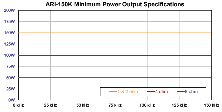
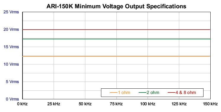
- ▸ Up to 150 W into low-impedance loads — delivers up to 150 W into 1–2 Ω loads, 100 W into 4 Ω, and 50 W into 8 Ω, with ≤8% distortion across the operating range.
- ▸ Built for MIL-STD-461 CS101 conducted susceptibility testing — injects low-frequency disturbances onto power and signal lines, typically driving an injection transformer or coupling network.
- ▸ Supports MIL-STD-461 RS101 radiated susceptibility testing — drives field coils and loop fixtures to evaluate low-frequency magnetic field immunity.
- ▸ Ideal for aerospace RTCA DO-160 Section 18 testing — provides the controlled low-frequency excitation required for airborne equipment susceptibility tests.
- ▸ Stable performance with ±5° phase response — maintains ±5° phase accuracy up to 75 kHz and ≤8% distortion for repeatable, reliable test results.
- ▸ Built-in overload, over-temperature, and over-current protection — safeguards the amplifier when driving coils, transformers, and custom fixtures with frequency-dependent impedance.
- ▸ 3U rack-mount design with wide-range AC input and three-year warranty — operates on 100–250 VAC with forced-air cooling and front-panel temperature/current monitoring.
ARI-150K Features
- ▸ Low-frequency power amplifier — for conducted and radiated susceptibility testing
- ▸ Frequency range 30 Hz to 150 kHz
- ▸ Up to 150 W into 1–2 Ω; 100 W into 4 Ω; 50 W into 8 Ω
- ▸ Designed for MIL-STD-461 CS101 and RS101
- ▸ Supports RTCA DO-160 Section 18 testing
- ▸ ≤8% total harmonic distortion
- ▸ ±5° phase response up to 75 kHz
- ▸ Overload, over-temperature, and over-current protection
- ▸ BNC input, dual 4 mm banana-jack outputs
- ▸ Wide-range 100–250 VAC input — forced-air cooled
- ▸ Front-panel temperature and output-current monitoring
- ▸ 3U rack-mount design; three-year warranty
ARI-150K Specifications
| Parameter | Specification |
|---|---|
| Model | ARI-150K |
| Type | Low-frequency power amplifier |
| Application | Conducted and radiated susceptibility testing |
| Standards | MIL-STD-461 (CS101, RS101), RTCA DO-160 (Section 18) |
| Frequency Range | 30 Hz to 150 kHz |
| Output Power | Up to 150 W (1–2 Ω), 100 W (4 Ω), 50 W (8 Ω) |
| Distortion | ≤8% |
| Phase Response | ±5° up to 75 kHz |
| DC Drift | < ±1.5 mV after 30 min |
| Input Impedance | 10 kΩ nominal |
| Output Impedance | 6.25 mΩ nominal |
| Protection | Over-temperature, over-current, improper-load safeguards |
| Input Connector | BNC (female) |
| Output Connectors | Two 4 mm banana-jack binding posts |
| AC Input Power | 100–250 VAC, 50/60 Hz (1000 VA max) |
| AC Input Connector | IEC C13 receptacle |
| Cooling | Forced air |
| Dimensions (H × W × D) | 6.125" × 19" × 23.25" (15.9 × 48.3 × 59 cm) |
| Rack Mount | 3U, 5.25" × 19" × 22.25" |
| Operating Temperature | 40°F to 104°F (5°C to 40°C) |
| Warranty | 3 years |
Load configuration: Output power depends on load impedance — choose the 1/2/4/8 Ω configuration based on the effective impedance of the injection device, cabling, and coupling network. Built-in protection guards against over-temperature, over-current, and improper load conditions.
-
What injection method is this amplifier typically used with (CS101 / DO-160 Sec 18)?
Most setups drive an injection transformer (or a coupling transformer) to place the disturbance voltage/current onto the EUT power leads while the EUT is powered through the appropriate LISN/coupling network. -
How do I choose the right output load configuration (1 Ω / 2 Ω / 4 Ω / 8 Ω) for my setup?
Choose based on the effective impedance of the injection device + cabling + coupling network seen by the amplifier; verify by measuring output current and voltage at the amplifier terminals under test conditions. -
How do I prevent amplifier shutdown or clipping when sweeping 30 Hz–300 kHz?
Keep the sweep within the minimum output capability curve, use stepwise level increases, and monitor output current / temperature; if current rises sharply at certain frequencies, it usually indicates fixture resonance or too-low effective impedance. -
Where should I measure level—at the amplifier output or at the EUT input?
For susceptibility testing, level control is typically based on what reaches the EUT line (via a monitor port/coupler, current probe, or measured line voltage), not just the amplifier terminals, because the injection network can add frequency-dependent loss. -
What signal source level is needed to drive the amplifier correctly?
Use a signal generator with enough headroom to achieve required output without overdriving; keep the generator within its low-distortion range and increase power using the amplifier rather than “hot” source levels. -
Can I use this amplifier to drive an RS101 loop/coil fixture for magnetic field susceptibility?
Yes—this type of low-frequency power amp is commonly used to drive field coils/loops, but you must confirm the coil’s impedance vs frequency and watch for resonances that can force excessive current. -
What output protection practices should I use with transformers and coils?
Use short, heavy-gauge leads, avoid open/short transitions while energized, and consider adding current limiting in the test plan (and, when appropriate, protective components in the fixture) to prevent abrupt load changes. -
How do I handle grounding and noise to avoid corrupting measurements at low frequencies?
Use a single-point ground strategy, keep high-current return paths short, separate measurement cabling from power cabling, and avoid ground loops between the amplifier, injection network, and measurement instruments. -
What instruments are typically paired with this amplifier for closed-loop leveling?
A typical chain includes a signal generator, power meter or RMS voltmeter, and/or a current probe with measurement receiver/scope, plus any directional coupler/monitor port provided by the injection network. -
What’s the practical impact of ≤8% distortion and phase response for susceptibility work?
In immunity tests, the goal is controlled stress on the EUT; distortion mainly affects waveform purity, so you ensure compliance by meeting the required test level at the EUT and keeping operation out of severe clipping where harmonics can create unintended excitation paths. -
What other Com-Power products are commonly paired with this amplifier for better control and measurement during susceptibility tests?
In addition to the amplifier, engineers often pair it with Com-Power power meters or RMS voltmeters (e.g., PMX or RMS series) to measure and verify actual output levels delivered to the injection network or EUT. These measurement instruments help ensure the amplifier’s output stays within test limits, especially when using coupling networks or coils whose impedance varies with frequency. Using real-time level verification improves repeatability and compliance confidence in CS101 / RS101 and RTCA DO-160 immunity tests. -
What other Com-Power products complement this amplifier for broader EMC testing and how are they used?Injection Transformers / Coupling Networks: Com-Power coupling devices such as CFT- and CN- series networks are used to inject disturbance voltages or currents into the device under test (DUT) lines when connected with this amplifier. They define the injection point and impedance environment for CS101/RS101 tests.Field Coils & Loop Fixtures: For magnetic field susceptibility (RS101 / DO-160 Sec 18), Com-Power field coils and magnetic loop fixtures convert amplifier output into a defined field at the DUT location.Power Line Impedance Stabilization Networks (LISNs): While this amplifier doesn’t directly use LISNs for output, LISNs are essential for conducted emission paths when measuring with receivers/EMI analyzers in adjacent tests or when using coupled setups.

Quote Request
Other EMC Test Equipment
- Absorbing Clamps
- Antenna Kits
- Antenna Masts - Automated and Manual
- Antennas
- Bulk Current Injection probes
- CDNs - Coupling Decoupling Network
- Comb Generators
- Conducted Immunity Test Systems
- Current Monitor Probes
- Current Probe Calibration Fixtures
- EM Clamps
- Feed Through Capacitor
- ISNs - Impedance Stabilization Network
- LISNs - Single Phase
- LISNs - TEMPEST
- LISNs - Three Phase
- Magnetic Field Generator
- Near Field Probes
- Power Amplifiers
- Pre-compliance Emissions Test Systems
- Preamplifiers
- Spectrum Analyzers
- Surge Generators
- System Controllers
- Transient Limiters
- Tripods For EMC
- Turntables