
10 kHz–400 MHz Bulk Current Injection Probe
- ▸ Bulk current injection (BCI) probe, 10 kHz–400 MHz — engineered for MIL-STD-461 (CS114/CS115/CS116) and RTCA DO-160 Section 20 conducted susceptibility tests, with efficient coupling that meets stringent test levels.
- ▸ 1.575" (40 mm) split-core window — clamps onto individual cables or whole bundles without disconnecting wiring, preserving installed cable behavior.
- ▸ 100 W continuous RF input via Type-N (female) connector — efficient enough to reach high-severity military and avionics test levels with modest amplifier headroom.
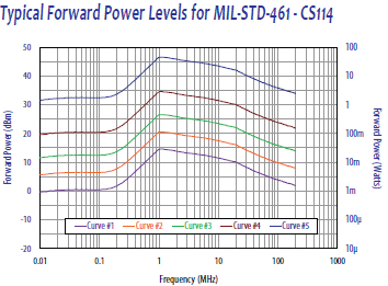
- ▸ Military electronics and ground systems — cable-level RF injection on vehicle, weapon, and command-and-control electronics tested to MIL-STD-461 CS114.
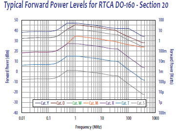
- ▸ Avionics and aerospace systems — conducted susceptibility per RTCA DO-160 Section 20 (Categories R, S, T, W, Y, Z) on flight-control, navigation, and communication LRUs.
- ▸ Industrial control, automotive, and rail subsystems — high-reliability electronics tested above the 100 MHz upper edge of IEC 61000-4-6 BCI use.
- ▸ Medical and mission-critical devices with long cable runs — supports cable-level RF injection on patient monitors, infusion systems, and other mission-critical equipment.
- ▸ Compatible with FCLC-400 calibration fixture and ACS-series amplifiers — Term-50-100W termination for full setup; three-year warranty.
CLCI-400 Features
- ▸ Frequency range 10 kHz to 400 MHz — extended band for military and avionics conducted susceptibility
- ▸ 1.575" (40 mm) window diameter — fits large cables and bundles
- ▸ Split-core ferrite design — easy clamp-on access without disconnecting cables
- ▸ Complies with MIL-STD-461 (CS114, CS115, CS116) and RTCA DO-160 Section 20
- ▸ 100 W continuous RF input power — reaches stringent military/avionics test severities
- ▸ Type-N (female) input connector — standard mate to RF power amplifier output
- ▸ Current injection and monitoring capability — one probe for both functions
- ▸ Maximum core temperature 284°F (140°C) — supports extended testing under thermal load
- ▸ Efficient coupling — typically < 60 W forward power needed to reach stringent test levels
- ▸ Rugged housing — 5.75" (146 mm) outer diameter, 2.75" (70 mm) width, 4.5 lbs (2.04 kg)
- ▸ Pairs with FCLC-400 calibration fixture for insertion loss, VSWR, and forward-power calibration
- ▸ Three-year manufacturer warranty
CLCI-400 Specifications
| Parameter | Specification |
|---|---|
| Model | CLCI-400 |
| Type | Bulk current injection (BCI) probe |
| Applicable Standards | MIL-STD-461 (CS114, CS115, CS116); RTCA DO-160 Section 20 |
| Frequency Range | 10 kHz to 400 MHz |
| Window Diameter | 1.575" (40 mm) |
| Outside Diameter | 5.75" (146 mm) |
| Width | 2.75" (70 mm) |
| Weight | 4.5 lbs (2.04 kg) |
| Input Connector | Type-N (female) |
| Maximum Input Power | 100 W (continuous) |
| Maximum Core Temperature | 284°F (140°C) |
| Core Design | Split-core ferrite (clamp-on) |
| Function | RF current injection and monitoring |
| Calibration Fixture | FCLC-400 (Com-Power) |
| Accessories | Term-50-100W termination, ACS-series power amplifiers |
| Warranty | 3 years |
Typical setup: Signal generator → ACS-series RF power amplifier → directional coupler / power meter → CLCI-400 injection probe → cable/EUT, with current monitoring to reproduce calibrated forward-power levels at each test frequency.
1. What problem does the CLCI-400 solve in EMC testing?
The CLCI-400 is used to intentionally inject RF current onto cables to evaluate how susceptible an electronic product is to conducted electromagnetic interference. It helps identify whether external RF disturbances on wiring can disrupt normal operation of the equipment under test (EUT).
2. In what types of test setups is the CLCI-400 most useful?
It is most useful in bulk current injection (BCI) setups where RF energy must be coupled onto complete cables or cable bundles without breaking or modifying the wiring. This is common in military, aerospace, avionics, and high-reliability industrial testing.
3. Which EMC standards typically require or recommend a bulk current injection probe like the CLCI-400?
The CLCI-400 is commonly used in conducted susceptibility tests defined in:
-
MIL-STD-461 (CS114, CS115, CS116)
-
RTCA DO-160 (Section 20)
These standards specifically call for current injection onto interconnecting cables rather than voltage injection at the power port.
4. How is bulk current injection different from conducted immunity testing with CDNs?
Bulk current injection couples RF energy magnetically onto cables using a clamp, while CDNs inject RF electrically through a defined impedance network. BCI is preferred when cables cannot be disconnected, when multiple conductors must be stressed together, or when the standard requires realistic cable coupling rather than controlled port injection.
5. How does the CLCI-400 differ from a LISN?
A LISN is used mainly for emissions measurement and power-line immunity, providing a controlled impedance at the EUT power input. The CLCI-400 does not stabilize impedance or measure noise; instead, it injects RF current onto signal, control, or power cables to simulate external electromagnetic disturbances.
6. How is the CLCI-400 different from a current monitoring probe?
Current monitoring probes are optimized for measurement accuracy and sensitivity, while the CLCI-400 is optimized for power handling and efficient current injection. Although the CLCI-400 can measure current, its primary purpose is stressing cables rather than precision monitoring.
7. When would an engineer choose the CLCI-400 instead of a voltage injection method?
Engineers choose the CLCI-400 when they need to replicate real-world RF coupling onto cables, such as exposure to nearby transmitters, radar, or onboard RF systems—conditions where interference enters via wiring rather than through power terminals.
8. What types of products are typically tested using the CLCI-400?
It is commonly used for testing:
-
Military and defense electronics
-
Avionics and aerospace systems
-
Industrial control equipment
-
Automotive and rail subsystems
-
Medical and mission-critical devices with long cable runs
9. Why is a split-core design important in a bulk current injection probe?
A split-core design allows the probe to be clamped around cables without disconnecting them. This saves setup time, reduces the risk of altering cable behavior, and better represents real-installation conditions required by many standards.
10. How does the CLCI-400 fit into a complete conducted susceptibility test system?
The CLCI-400 is typically used with a signal generator, RF power amplifier, directional coupler or power meter, and a calibration fixture. Together, these components ensure the required current level is injected accurately and repeatably across the test frequency range.
11. Why is calibration critical when using the CLCI-400?
Calibration ensures that the forward RF power delivered to the probe results in the intended current on the cable. Without calibration, test results may not meet standard requirements or be reproducible between labs.
12. Can the CLCI-400 be used for pre-compliance testing?
Yes. Many engineers use it during design validation to identify susceptibility issues early, allowing cable routing, filtering, or shielding improvements before formal compliance testing.
13. How does bulk current injection testing improve product robustness?
By forcing controlled RF currents onto cables, the test reveals weak points in grounding, shielding, filtering, and internal circuit immunity—helping designers harden products against real-world electromagnetic environments.
14. What makes the CLCI-400 suitable for high-severity immunity testing?
Its efficient coupling over a wide frequency range allows required test levels to be achieved without excessive amplifier power, making it practical for stringent military and aerospace immunity categories.
15. Is the CLCI-400 intended for emissions testing?
No. The CLCI-400 is primarily an immunity tool, not an emissions measurement device. While it can monitor current, emissions compliance typically relies on LISNs, antennas, and EMI receivers rather than injection probes.
16. How is the Com-Power FCLC-400 calibration fixture used with the CLCI-400, and why is it important?
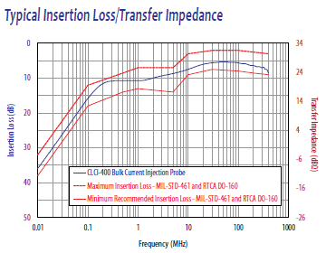
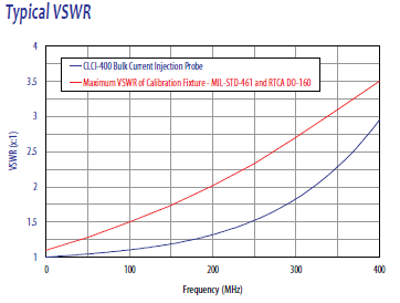
The Com-Power FCLC-400 calibration fixture is used to calibrate and verify the current injection levels of the CLCI-400 before performing immunity tests. The fixture creates a controlled, coaxial transmission path that allows the probe to clamp around a centered conductor while maintaining consistent impedance. This setup enables accurate determination of insertion loss and establishes the relationship between forward RF power and induced current. Using the FCLC-400 ensures that the injected current during testing truly matches the levels required by standards such as MIL-STD-461 and RTCA DO-160, making test results repeatable, traceable, and defensible during audits or compliance reviews.


Quote Request
Other EMC Test Equipment
- Absorbing Clamps
- Antenna Kits
- Antenna Masts - Automated and Manual
- Antennas
- Bulk Current Injection probes
- CDNs - Coupling Decoupling Network
- Comb Generators
- Conducted Immunity Test Systems
- Current Monitor Probes
- Current Probe Calibration Fixtures
- EM Clamps
- Feed Through Capacitor
- ISNs - Impedance Stabilization Network
- LISNs - Single Phase
- LISNs - TEMPEST
- LISNs - Three Phase
- Magnetic Field Generator
- Near Field Probes
- Power Amplifiers
- Pre-compliance Emissions Test Systems
- Preamplifiers
- Spectrum Analyzers
- Surge Generators
- System Controllers
- Transient Limiters
- Tripods For EMC
- Turntables