
Conducted Immunity Testing Probe
- ▸ Bulk current injection (BCI) probe, 10 kHz–100 MHz — injects RF common-mode current onto cables for IEC 61000-4-6 conducted immunity testing without breaking the cable run.
- ▸ 1.575" (40 mm) split-core window — clamps directly around individual cables or bundles, ideal where a commercially available CDN for the port type does not exist.
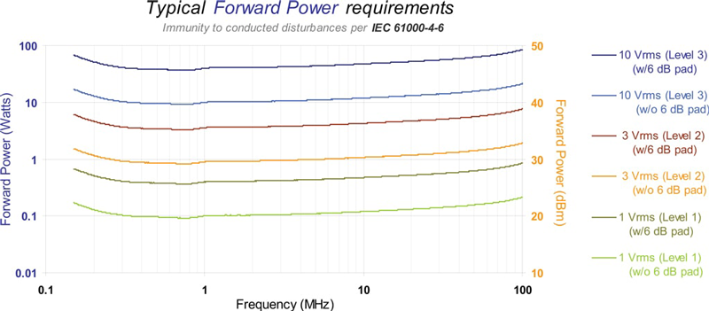
- ▸ 100 W continuous RF input via Type-N (female) connector — efficient coupling delivers full IEC 61000-4-6 test levels in the 150 kHz–80 MHz primary band and the 80–230 MHz extended band coverage of the probe.
- ▸ IEC 61000-4-6 / CISPR 16-1-2 conducted immunity testing — the standards-preferred substitution when no qualified CDN exists, with current monitoring per the standard.
- ▸ Industrial control and automation cables — PLC field wiring, sensor harnesses, fieldbus drops, and motor-feedback cables where the cable cannot be broken to insert a CDN.
- ▸ Medical electrical equipment — patient cables, monitor leads, and power-line/IO bundles tested per IEC 60601-1-2 (which invokes IEC 61000-4-6).
- ▸ Automotive component bench testing — supports cable-level RF injection of ECUs, harnesses, and sub-system bench setups where standards permit BCI in the 10 kHz–100 MHz range.
- ▸ Compatible with FCLC-100 calibration fixture and ACS-series amplifiers — ADA-515-2 150 Ω / 50 Ω adapters and Term-50-100W termination for full IEC 61000-4-6 level setup; three-year warranty.
CLCI-100 Features
- ▸ Frequency range 10 kHz to 100 MHz — covers IEC 61000-4-6 conducted RF immunity band
- ▸ 1.575" (40 mm) window diameter — fits large cables and bundles
- ▸ Split-core ferrite design — easy clamp-on access without disconnecting cables
- ▸ Complies with IEC 61000-4-6 and CISPR 16-1-2
- ▸ 100 W continuous RF input power — supports stringent immunity test levels
- ▸ Type-N (female) input connector — standard mate to RF power amplifier output
- ▸ Current injection and monitoring capability — one probe for both functions
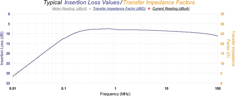
- ▸ 1:1 turns ratio — accurate current transfer and predictable transfer impedance
- ▸ Maximum core temperature 284°F (140°C) — supports extended testing under thermal load
- ▸ Rugged housing — 5.75" (146 mm) outer diameter, 2.75" (70 mm) width, 4.5 lbs (2.04 kg)
- ▸ Pairs with FCLC-100 calibration fixture for insertion loss and forward-power calibration
- ▸ Three-year manufacturer warranty
CLCI-100 Specifications
| Parameter | Specification |
|---|---|
| Model | CLCI-100 |
| Type | Bulk current injection (BCI) probe |
| Applicable Standards | IEC 61000-4-6, CISPR 16-1-2 |
| Frequency Range | 10 kHz to 100 MHz |
| Window Diameter | 1.575" (40 mm) |
| Outside Diameter | 5.75" (146 mm) |
| Width | 2.75" (70 mm) |
| Weight | 4.5 lbs (2.04 kg) |
| Input Connector | Type-N (female) |
| Maximum Input Power | 100 W (continuous) |
| Maximum Core Temperature | 284°F (140°C) |
| Turns Ratio | 1:1 |
| Core Design | Split-core ferrite (clamp-on) |
| Function | RF current injection and monitoring |
| Calibration Fixture | FCLC-100 (Com-Power) |
| Accessories | ADA-515-2 150 Ω/50 Ω adapters, Term-50-100W termination, ACS-series amplifiers |
| Warranty | 3 years |
Typical setup: Signal generator → ACS-series RF power amplifier → (optional directional coupler / power meter) → CLCI-100 injection probe → cable/EUT, with current monitoring per IEC 61000-4-6 to keep induced current within specified limits.
1. What is the CLCI-100 used for?
The CLCI-100 Bulk Current Injection Probe is used to inject RF energy onto cables/cable bundles to evaluate conducted RF immunity (susceptibility) and to monitor induced current when needed.
2. How is the CLCI-100 different from the CLCI-400?
The biggest practical difference is the frequency focus:
-
CLCI-100 is designed for 10 kHz to 100 MHz and is positioned for IEC 61000-4-6 style conducted RF immunity work.
-
CLCI-400 extends far higher (to 400 MHz) and is used heavily in higher-frequency cable current injection applications.
3. Which standards and test types is the CLCI-100 most associated with?
It’s specifically aligned to IEC 61000-4-6 conducted RF immunity, and the manual also notes it can be used in other conducted susceptibility contexts depending on the test plan.
4. When should you use an injection clamp like the CLCI-100 instead of a CDN?
Per IEC 61000-4-6 guidance, an injection clamp is used when there is no commercially available CDN for the port type you need to test.
5. Why isn’t an injection clamp a “drop-in replacement” for a CDN?
A CDN both couples RF and also provides decoupling + a defined impedance environment. A clamp does not provide those decoupling/impedance functions, so the cable current behavior is less controlled and must be verified/managed.
6. Do you need a current monitoring probe when using the CLCI-100?
Often, yes. Because a clamp does not establish the required impedance and the current can vary by cable/EUT conditions, IEC 61000-4-6 practice calls for monitoring so current does not exceed the maximum required current.
7. How is the RF current actually coupled onto the cable?
The probe is essentially a toroidal transformer: when injecting, the probe acts like the primary and the cable(s) through the aperture act like the secondary—no direct electrical contact to the conductor is required.
8. What’s the role of the Com-Power FCLC-400 calibration fixture with the CLCI-100?
The FCLC-400 provides a controlled coaxial-type arrangement so the probe can be calibrated for insertion/coupling loss and transfer impedance, and it’s also used to set/establish test drive levels (into defined systems) before testing.
9. Does the CLCI-100 use the same FCLC-400 fixture as other Com-Power clamps?
Yes—the CLCI-100 is designed to be compatible with the FCLC-400, and the CLCI-100 manual includes detailed “using the probe with the fixture” sections.
10. Why does the IEC 61000-4-6 calibration setup often use a 150 Ω system (not 50 Ω)?
For IEC 61000-4-6 calibration, the manual describes calibrating into a 150 Ω system using 150 Ω to 50 Ω adapters on the fixture, because that matches how the standard defines parts of the test generator / calibration method.
11. What are “Method A” vs “Method B” during IEC 61000-4-6 level calibration?
The manual describes two acceptable approaches:
-
Method A: record the signal generator output setting vs frequency during calibration, then replay those settings during test.
-
Method B: record forward power vs frequency (using a directional coupler + power meter/sensor) during calibration, then reproduce forward power during test.
12. How do ACS-series power amplifiers fit into a complete CLCI-100 setup?
A typical complete setup is:
Signal generator → ACS-series RF power amplifier → (directional coupler / power measurement, if using forward-power method) → CLCI-100 injection clamp → cable bundle/EUT, with measurement gear (spectrum analyzer/EMI receiver) used during calibration and/or monitoring.
Com-Power positions its ACS series as geared for IEC 61000-4-6 conducted immunity testing and offers multiple models/frequency bands depending on needed range/power.
13. Which ACS-series amplifier frequency ranges commonly pair with IEC 61000-4-6 work?
Common published ACS examples include models covering bands such as:
-
150 kHz to 230 MHz (ACS-230 series variants)
-
150 kHz to 250 MHz (ACS-250-100W)
For the CLCI-100 specifically (10 kHz–100 MHz), many labs select an amplifier that cleanly covers their intended test band and power needs without unnecessary extra range.
14. What other accessories typically complete the system (besides the clamp and amplifier)?
Typical supporting items include attenuators, terminations, directional coupler, adapters, and the calibration fixture, depending on whether you’re calibrating via 150 Ω or 50 Ω methods.
15. how do teams usually calibrate before testing?
A typical workflow looks like this:
-
Build a controlled calibration setup using the FCLC-400 fixture and the required adapters/attenuators for the intended method (150 Ω system for IEC 61000-4-6 calibration).
-
Establish target levels (the measured level used for calibration, not just the “headline” Vrms) and ensure measurement chain corrections (like attenuator offsets) are accounted for.
-
Sweep discrete test frequencies and record either signal generator settings (Method A) or forward power (Method B) that achieve the target measured level at each frequency.
-
Validate the RF power chain is behaving linearly (avoid saturated amplifier operation) so the calibration remains trustworthy.
-
Move to the EUT setup and reproduce the calibrated levels while monitoring the injected current as needed.
16. What are the most common mistakes during BCI / clamp-based calibration?
Common issues that cause bad calibrations or inconsistent results include:
-
Treating a clamp like a CDN (forgetting the clamp doesn’t create the same controlled impedance/decoupling environment).
-
Not monitoring current during the actual test, especially when the EUT/cable impedance differs from calibration conditions.
-
Incorrect attenuator/adapter corrections (calibrating to the wrong measured level because offsets weren’t applied correctly).
-
Amplifier compression/saturation (calibration points look “okay” but can’t be reproduced consistently because the amplifier is not operating linearly).
-
Poor bonding to the ground plane / inconsistent physical setup between calibration and test (fixture placement and bonding approach matter for repeatability).
-
Mixing Method A and Method B assumptions (e.g., calibrate by forward power but attempt to run by generator settings without re-validating the chain).
17. Can the CLCI-100 be used for current monitoring too?
Yes, it supports current injection & monitoring capability, and its transfer-impedance factor concept is used to convert measured RF voltage at a 50 Ω instrument input into current units.
18. What’s the key practical takeaway about the CLCI-100’s frequency range?
The 10 kHz–100 MHz range makes it a strong fit for lower-to-mid frequency conducted RF immunity work where clamp injection is acceptable/required and where test teams prioritize repeatable level-setting, current oversight, and efficient power coupling in that band.


Quote Request
Other EMC Test Equipment
- Absorbing Clamps
- Antenna Kits
- Antenna Masts - Automated and Manual
- Antennas
- Bulk Current Injection probes
- CDNs - Coupling Decoupling Network
- Comb Generators
- Conducted Immunity Test Systems
- Current Monitor Probes
- Current Probe Calibration Fixtures
- EM Clamps
- Feed Through Capacitor
- ISNs - Impedance Stabilization Network
- LISNs - Single Phase
- LISNs - TEMPEST
- LISNs - Three Phase
- Magnetic Field Generator
- Near Field Probes
- Power Amplifiers
- Pre-compliance Emissions Test Systems
- Preamplifiers
- Spectrum Analyzers
- Surge Generators
- System Controllers
- Transient Limiters
- Tripods For EMC
- Turntables