
Tempest LISN For Power Line Conducted Emissions Compliance Testing
-
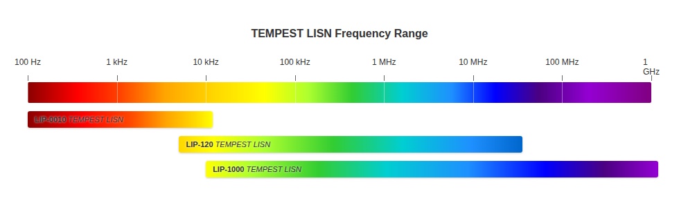
The Com-Power LIP-1000 is a high-frequency Tempest LISN, engineered for conducted emissions testing in the 1 MHz to 1 GHz range.
-
It provides a stable and defined 50Ω impedance, ensuring consistent and repeatable results during government and military TEMPEST evaluations.
-
By isolating the Equipment Under Test (EUT) and measurement circuits from the mains, the LISN minimizes external power source influence.
-
Its dual-conductor design reduces cross-coupling between lines, enhancing accuracy for sensitive testing environments.
-
The LIP-1000 couples disturbance voltages to its RF measurement ports, allowing direct connection to EMI receivers or spectrum analyzers.
-
Air-core inductors are used to eliminate saturation effects, maintaining performance stability across the entire frequency band.
-
It supports both AC and DC systems, handling up to 270 VAC / 380 VDC and 10 A continuous current, making it versatile for a wide range of setups.
-
Supplied with NIST-traceable calibration data and available ISO-17025 accredited calibration, it meets the highest compliance assurance standards.
-
Compact, lightweight, and backed by a three-year warranty, the LIP-1000 is built for reliability in demanding TEMPEST testing laboratories.
Features
- ▸ High-frequency TEMPEST LISN, 1 MHz to 1 GHz — engineered for the band where modern high-speed digital circuits, USB/HDMI interfaces, RF clock oscillators, and encrypted communication buses generate their most significant compromising emanations.
- ▸ 23 µH low-inductance air-core network — optimized for broadband performance up to 1 GHz; air-core construction eliminates magnetic saturation under all operating conditions.
- ▸ 50 Ω impedance (+30 / −20 Ω) — defined, calibrated impedance presented to the EUT across the full 1 MHz–1 GHz band, ensuring measurements are repeatable across test sessions and laboratories.
- ▸ > 40 dB isolation (mains-to-EUT and line-to-line) — substantially attenuates ambient power line noise so that low-level compromising signals from the EUT are not masked; critical for high-confidence security assessments.
- ▸ < 2.5 dB insertion loss across the full band — preserves signal integrity for accurate TEMPEST evaluations even at the upper end of the operating range.
- ▸ Dual-conductor design (Line and Neutral) — covers both AC power conductors simultaneously, enabling detection of differential-mode and common-mode compromising signals on both leads.
- ▸ 10 A continuous current rating, 270 VAC / 380 VDC voltage rating — supports the full range of equipment found in classified processing environments.
- ▸ 50 Ω BNC (female) RF measurement port — standard interface for direct connection to TEMPEST-grade EMI receivers and spectrum analyzers; appropriate for the high-frequency RF measurement application.
- ▸ Coaxial N-type EUT connection with universal receptacle adapter included — preserves measurement integrity at the EUT side while still accommodating standard plug-in equipment via the included adapter.
- ▸ Lightweight, portable form factor — 4.1 × 8.1 × 14.4 in (10.5 × 20.7 × 36.5 cm), 5.5 lbs (2.5 kg); the most portable LISN in the TEMPEST series for field assessments and on-site security testing.
- ▸ Complementary to LIP-0010 and LIP-120 — together the three TEMPEST LISNs deliver uninterrupted 100 Hz to 1 GHz coverage; common 10 A / 380 VDC ratings allow seamless transitions between units without EUT rewiring.
- ▸ Individually NIST-traceable calibrated — impedance, insertion loss, and isolation data shipped with each unit. ISO 17025 accredited calibration available on request.
- ▸ Three-year standard warranty — backed by manufacturer support.
Specifications
| Model | LIP-1000 |
|---|---|
| Product Type | TEMPEST High-Frequency LISN, dual-conductor (Line & Neutral) |
| Standard | TEMPEST |
| Application | High-frequency TEMPEST conducted emissions tests |
| Frequency Range | 1 MHz – 1 GHz |
| Inductance | 23 µH (air-core) |
| Impedance | 50 Ω (+30 / −20 Ω) |
| Insertion Loss | < 2.5 dB |
| Isolation (Mains to EUT) | > 40 dB |
| Isolation (Line to Line) | > 40 dB |
| Number of Lines | 2 (Line & Neutral) |
| Max Voltage | 270 VAC (50/60 Hz) / 380 VDC |
| Max Current | 10 A continuous |
| RF Measurement Port | BNC (female), 50 Ω |
| EUT Power Connector | Coaxial N-type (universal receptacle adapter included) |
| Mains Input | IEC C13 receptacle |
| Dimensions (H × W × D) | 4.1 × 8.1 × 14.4 in (10.5 × 20.7 × 36.5 cm) |
| Weight | 5.5 lbs (2.5 kg) |
| Operating Temperature | 5 °C to 40 °C |
| Calibration | Individual, NIST-traceable; ISO 17025 accredited available on request |
| Warranty | Three-year standard warranty |
All values are typical, unless specified. All specifications subject to change without notice.


| Title | Link |
|---|---|
| LIP-1000 Datasheet | View PDF |
🔍 Not Sure This Is The Right LISN?
Compare all 25 Com-Power LISN models side-by-side with our interactive selection tool. Filter by current, voltage, frequency, and standards to find your perfect match.
Compare All LISN Models →LIP-1000 TEMPEST RF Line Impedance Stabilization Network FAQs
What is the LIP-1000 and what TEMPEST testing application is it designed for?
The LIP-1000 is a dual-conductor, 50Ω, 23 μH Line Impedance Stabilization Network (LISN) designed specifically for TEMPEST testing. It covers 1 MHz to 1 GHz and provides the measurement platform required for performing high-frequency power line conducted emissions compliance testing. It provides a defined, stable impedance reference for the EUT, isolates the EUT from the power source, provides isolation between the power lines to minimize cross-coupling, and couples high-frequency disturbance voltages to the coaxial measurement ports for connection to a TEMPEST measurement receiver or spectrum analyzer.
Why does the LIP-1000 cover 1 MHz to 1 GHz and what TEMPEST emissions are captured in this frequency range?
The 1 MHz to 1 GHz range is the high-frequency RF portion of the TEMPEST conducted emissions spectrum. Information-bearing emissions from digital equipment appear on power leads as RF energy conducted through the power supply input filter and back onto the mains. Typical emission sources include processor core clock harmonics, high-frequency bus transactions, display pixel clock harmonics, memory interface signals, and RF interference from internal wireless modules coupling onto DC supply rails. The 1 GHz upper limit captures harmonics of modern processors operating at several hundred MHz and fundamental frequencies of some on-chip wireless modules.
What is the significance of the 23 μH inductance in the LIP-1000?
The LIP-1000 uses a 23 μH inductance, much smaller than the 1.37 mH of the LIP-120 and 2.8 mH of the LIP-0010. At 1 MHz, 23 μH presents approximately 145 Ω of inductive reactance, well above 50Ω and ensuring the 50Ω resistive termination dominates the measurement impedance from 1 MHz upward. At lower frequencies, 23 μH presents insufficient reactance to establish the 50Ω impedance, which is why the LIP-1000's range begins at 1 MHz. The impedance tolerance of 50Ω (+30Ω/-20Ω) reflects the wider variation that occurs across the very broad 1 MHz to 1 GHz range as parasitic capacitances and lead inductances interact at high frequencies.
What is the LIP-1000's impedance tolerance of 50Ω (+30Ω/-20Ω) and how does it affect TEMPEST measurements?
The impedance tolerance reflects the inherently wider variation that occurs across a decade-wide frequency range from 1 MHz to 1 GHz. At lower frequencies, the inductor's inductive reactance establishes the 50Ω reference. At higher frequencies approaching 1 GHz, parasitic capacitances and transmission line effects cause the impedance to deviate from the ideal 50Ω value. The individual unit calibration data supplied with each LIP-1000 provides the actual impedance versus frequency for that specific unit, allowing accurate corrections when the impedance deviates from nominal 50Ω at any specific frequency.
What power system types can the LIP-1000 be used with and what are its voltage and current ratings?
The LIP-1000 is rated for AC and DC operation and accommodates DC, single-phase, split-phase, and three-phase AC systems. Maximum AC voltage is 270 V RMS line-to-ground at 50-60 Hz; maximum DC voltage is 380 V DC; maximum current is 10 A continuous per line. For three-phase AC systems, two LIP-1000 LISNs are used simultaneously. These ratings are consistent with the LIP-120, ensuring the LIP-1000 can be used on the same EUT configuration without any power supply or EUT connection changes when switching between instruments during a complete TEMPEST characterization.
What connectors does the LIP-1000 use on the EUT power output port and how does this differ from the LIP-120?
The LIP-1000 EUT power output port uses coaxial N-type connectors rather than the universal multi-configuration receptacle of the LIP-120. The coaxial N-type EUT port connectors provide superior RF performance at high frequencies up to 1 GHz, minimizing stray inductance and parasitic coupling that would degrade the LISN impedance characteristic at the upper end of the range. The LIP-1000 is supplied with a coaxial N-type to universal power receptacle adapter that accommodates almost any EUT plug without additional adapters, maintaining broad EUT compatibility while preserving RF connection quality required for 1 GHz operation.
What RF measurement port connectors does the LIP-1000 use and how do they differ from the LIP-0010 and LIP-120?
The LIP-1000 RF measurement ports use BNC female connectors rather than the N-Type female connectors of the LIP-0010 and LIP-120. BNC connectors rated to approximately 4 GHz are the standard connection interface on most RF spectrum analyzers, EMI receivers, and TEMPEST measurement receivers for inputs in the 1 MHz to 1 GHz range. Using BNC on the LIP-1000 measurement ports matches the standard input connector type of instruments most commonly used in this frequency range, eliminating the need for N-type to BNC adapters. The mains power input retains the IEC C13 receptacle standard across all three LIP-series models.
What isolation does the LIP-1000 provide between its mains port and EUT port, and between its two power lines?
The LIP-1000 provides greater than 40 dB of isolation both from mains port to EUT port and between its two power lines across the full 1 MHz to 1 GHz range. This high and consistent isolation is essential at RF frequencies where stray coupling through parasitic capacitance and mutual inductance between conductors would otherwise be significant. The greater than 40 dB mains isolation prevents the RF conducted noise of the facility power supply from contaminating measurements, and the greater than 40 dB line-to-line isolation prevents cross-coupling of emissions between the two measured power conductors.
What insertion loss does the LIP-1000 introduce and how does it vary across the 1 MHz to 1 GHz range?
The LIP-1000 specifies insertion loss of less than 2.5 dB across its operating range. The typical insertion loss data shows the LISN factor starting near zero at 1 MHz, increasing moderately through the mid-range, and reaching up to approximately 2.5 dB at certain higher frequencies as impedance mismatch effects and network resonances influence transmission. The individual unit calibration data provides the precise frequency-dependent correction that must be applied to measurement receiver readings to obtain the true disturbance voltage on the EUT power lead.
Why are air-core inductors used in the LIP-1000 and what advantage do they provide at high RF frequencies?
Air-core inductors prevent magnetic saturation under DC bias and eliminate core-related losses and nonlinearity at high RF frequencies. Ferromagnetic core materials exhibit frequency-dependent permeability and loss characteristics that become significant at frequencies in the tens of MHz and above, causing impedance deviation and introducing nonlinear distortion into the measurement circuit. Air-core inductors maintain consistent inductance and Q factor across the full 1 MHz to 1 GHz band and maintain the specified 23 μH value at 10 A DC bias without saturation effects.
How does the LIP-1000 complete the Com-Power TEMPEST LISN series?
The LIP-1000 is the high-frequency instrument completing the three-model series: LIP-0010 (100 Hz to 10 kHz), LIP-120 (5 kHz to 1 MHz), LIP-1000 (1 MHz to 1 GHz). Together they cover 100 Hz to 1 GHz continuously with verified overlap regions at 5–10 kHz and at 1 MHz. The LIP-1000 is used last in the measurement sequence, covering the RF portion where processor clock harmonics and bus signals appear, and where TEMPEST limits can be most stringent because adversary receivers in this frequency range can exploit narrowband signals at lower power levels.
What types of information-processing equipment are most commonly evaluated using the LIP-1000?
The LIP-1000 evaluates the same categories of classified equipment as the LIP-120 but is specifically valuable for devices with high-frequency digital circuits operating at processor speeds of 100 MHz and above. Modern processor-based equipment, GPUs, high-speed memory interfaces, network interface controllers operating at gigabit speeds, and equipment with on-chip wireless modules such as Bluetooth or Wi-Fi all generate power lead emissions in the 1 MHz to 1 GHz range that are captured by the LIP-1000.
How is the LIP-1000 connected in a typical TEMPEST RF conducted emissions test session?
The LIP-1000 mounting plate is bonded to the facility earth. The facility power source connects to the IEC C13 mains input. The EUT connects to the coaxial N-type to universal power receptacle adapter installed in the coaxial EUT port connectors. A 50Ω coaxial cable connects one BNC measurement port to the TEMPEST measurement receiver configured for 1 MHz to 1 GHz. The second BNC port is terminated into 50Ω. The EUT is operated in its representative mission configuration while the receiver sweeps 1 MHz to 1 GHz recording the RF emission spectrum on each power conductor.
What are the physical dimensions and weight of the LIP-1000?
The LIP-1000 measures 4.1″ H × 8.1″ W × 14.4″ D (104.5 × 206.9 × 365 mm) and weighs 5.5 lbs (2.5 kg). It is the smallest and lightest of the three LIP-series TEMPEST LISNs (LIP-120: 8.5 lbs; LIP-0010: 27.5 lbs), directly reflecting that 23 μH requires far less wire and core geometry than 1.37 mH or 2.8 mH. Operating temperature is 40°F to 104°F (5°C to 40°C).
What safety precautions apply when connecting and operating the LIP-1000?
The protective earth must be connected before applying power; the input power configuration must be verified before making connections; all connections must be secured before the supply is energized; and all connections must be de-energized before removing any connectors. Inserting or removing power connectors while the supply is live can result in electrical shock at up to 270 V AC RMS or 380 V DC. The coaxial N-type EUT port connectors and the universal power receptacle adapter must also be secured before energizing the power source.
How is the LIP-1000 calibrated and what calibration documentation is provided?
Every LIP-1000 is individually calibrated per its relevant TEMPEST LISN requirements. Impedance, insertion loss, mains-to-EUT port isolation, and line-to-line isolation data are supplied with each unit along with a certificate of calibration. ISO 17025 accredited calibration is available upon request. The individual calibration data is particularly important for the LIP-1000 because the impedance tolerance of 50Ω (+30Ω/-20Ω) allows significant per-unit variation at high frequencies, making the specific unit's calibration data essential for accurate assessments above 100 MHz.
How is the LIP-1000 used at a government TEMPEST test facility to evaluate a high-speed classified network server for RF conducted emissions?
The server is connected to the LIP-1000 on its power input and operated under a representative network traffic load exercising all processor cores, memory channels, and network interface controllers simultaneously, since maximum activity produces the highest power lead RF emissions. The TEMPEST measurement receiver sweeps 1 MHz to 1 GHz on each power conductor. Emission peaks corresponding to processor clock frequencies, memory bus frequencies, and network interface operating frequencies are evaluated against the applicable TEMPEST RF conducted emissions limits using the LIP-1000 individual calibration data to convert receiver readings to true disturbance voltage values.
What is a typical real-world scenario where the LIP-1000 reveals RF conducted emissions that were not visible with the LIP-120?
A common scenario: a secure workstation passes its LIP-120 evaluation across 5 kHz to 1 MHz but then fails the LIP-1000 evaluation above 100 MHz. The switching power supply harmonics below 1 MHz were compliant and correctly captured by the LIP-120, but the processor core at 2.4 GHz has a 400 MHz harmonic conducted back onto the supply rail at a level exceeding the TEMPEST limit — entirely invisible to the LIP-120 because it falls above 1 MHz. The LIP-1000 measurement reveals the 400 MHz emission, allowing the TEMPEST engineer to evaluate whether an additional power supply input filter with sufficient RF rejection above 100 MHz can reduce the emission to a compliant level.
How do intelligence community contractors use the LIP-1000 during product certification to demonstrate RF conducted emissions compliance?
After completing LIP-0010 and LIP-120 measurements, the LIP-1000 is connected to the same EUT for the RF portion of the characterization from 1 MHz to 1 GHz. The EUT is operated in each intended mode: idle, maximum processing load, network communication, display output, and cryptographic processing modes. The LIP-1000 records RF power lead emissions in all modes and the worst-case emission at each frequency is used for the limit comparison. The complete three-instrument data set covering 100 Hz to 1 GHz forms the conducted emissions chapter of the TEMPEST certification report submitted to the approving authority.
How is the LIP-1000 used in a TEMPEST countermeasure effectiveness verification after a power line filter is installed?
When a classified system fails TEMPEST RF conducted emissions testing with the LIP-1000 and a power line filter is installed as a countermeasure, the LIP-1000 is connected on the facility side of the filter for verification. RF conducted emissions sweeps from 1 MHz to 1 GHz are repeated in the same EUT operational modes that produced the original failure. Emission levels with the filter in place are compared against the TEMPEST limit and against the original pre-filter measurements to quantify the filter's insertion loss at the specific failing frequencies. If the filter brings all emissions below the applicable limit with adequate margin, the system is accepted with the filter as a permanent installed countermeasure.

Quote Request
Other EMC Test Equipment
- Absorbing Clamps
- Antenna Kits
- Antenna Masts - Automated and Manual
- Antennas
- Bulk Current Injection probes
- CDNs - Coupling Decoupling Network
- Comb Generators
- Conducted Immunity Test Systems
- Current Monitor Probes
- Current Probe Calibration Fixtures
- EM Clamps
- Feed Through Capacitor
- ISNs - Impedance Stabilization Network
- LISNs - Single Phase
- LISNs - TEMPEST
- LISNs - Three Phase
- Magnetic Field Generator
- Near Field Probes
- Power Amplifiers
- Pre-compliance Emissions Test Systems
- Preamplifiers
- Spectrum Analyzers
- Surge Generators
- System Controllers
- Transient Limiters
- Tripods For EMC
- Turntables