
16 Amp Three-Phase Line Impedance Stabilization Network
- Provides CISPR-compliant 50/250 µH +5Ω network for stable three-phase conducted EMI testing.
- Supports 9 kHz–30 MHz measurements with consistent impedance and high isolation accuracy.
- Handles up to 16A per line, suitable for low-power or prototype three-phase EUT evaluations.
- Offers remote or local line switching for safe, repeatable EMI receiver connection control.
- Uses air-core inductors to prevent saturation and ensure reliable results under load conditions.
- Ideal for compliance testing to CISPR 16-1-2 and ANSI C63.4 for commercial three-phase devices.
- Useful in labs testing drives, controls, and instrumentation requiring stable line impedance.
- Supports real-world EMC approval workflows by ensuring accurate disturbance-voltage capture.
- Includes NIST-traceable calibration for impedance, phase, isolation, and insertion loss.
- ISO 17025 accredited calibration available on request for formal compliance requirements.
Features
- ▸ Lowest-current LI-3P-2X three-phase V-AMN LISN, 16 A per line — suited for small three-phase motors, laboratory instruments, low-power PLCs, LED lighting drivers, and small industrial control panels.
- ▸ 9 kHz to 30 MHz frequency range — covers the extended CISPR / ANSI commercial conducted emissions band reaching down to 9 kHz; full coverage for the latest CISPR 16-1-2 / ANSI C63.4 revisions and product standards that mandate measurements starting from 9 kHz (LED drivers, switch-mode power supplies, solar inverters, EV chargers, and medical devices).
- ▸ Fully compliant with CISPR 16-1-2 and ANSI C63.4 (extended range) — the 50 Ω / 50/250 μH +5 Ω V-AMN four-conductor network is calibrated to the standard, accepted by accredited EMC test laboratories worldwide.
- ▸ Four-conductor design covers L1, L2, L3, and Neutral — supports both Delta (3-wire) and Wye (4-wire) three-phase configurations; one independent stabilization network per conductor.
- ▸ 16 A per line current rating with 25 A power connectors — matched to the EUT current draw range for this model in the 2X Series.
- ▸ High voltage rating: 865 Vrms line-to-line, 500 Vrms line-to-ground, 600 VDC — supports worldwide three-phase systems found in commercial and industrial applications.
- ▸ 50/60 Hz mains support
- ▸ Air-core inductors prevent saturation — air-core construction keeps inductance constant at all currents up to the 16 A rating, ensuring the LISN impedance and emissions measurement remain calibrated.
- ▸ Insertion loss < 11 dB above 150 kHz; isolation > 40 dB above 50 kHz — well-controlled signal path for accurate emissions measurement and effective decoupling of the EUT from facility power line noise.
- ▸ Built-in bypassable transient limiter with dual 5 dB attenuation/impedance matching pads — selectable receiver protection plus diagnostic flexibility; bypass for direct measurement when receiver protection is not required.
- ▸ Remote line switching via RLI V2.0 fiber optic interface — USB-connected interface unit with optical isolation switches between L1, L2, L3, and N from the control room without entering the test setup; enables fully automated test sequences.
- ▸ Manual front-panel line selection also provided — backup operation without the remote interface, useful for setup, manual diagnostics, and bench-top pre-compliance work.
- ▸ 50 Ω N-type female RF connector — standard interface for direct connection to EMI receivers and spectrum analyzers.
- ▸ Passive cooling via louvered panels and top-mounted air outlets — quiet operation appropriate for the low-power, low-current applications targeted by this model.
- ▸ Individually calibrated — each unit ships with calibration data; ISO 17025 accredited calibration available on request.
- ▸ Three-year standard warranty — backed by manufacturer support.
Specifications
| Model | LI-3P-216 |
|---|---|
| Series | 2X Series — Four-conductor 50 Ω / 50/250 μH +5 Ω V-AMN, CISPR 16-1-2 / ANSI C63.4 |
| Standards Compliance | CISPR 16-1-2 (CE) & ANSI C63.4 (FCC) — Extended range |
| Application | Extended-range commercial three-phase conducted emissions tests (9 kHz capable) |
| Frequency Range | 9 kHz – 30 MHz |
| Network Type | 50 Ω, 50/250 μH +5 Ω V-AMN, four-conductor (air-core) |
| Current Rating (per line) | 16 A |
| Power Connector Rating | 25 A |
| Max AC Voltage (Line-to-Line) | 865 Vrms |
| Max AC Voltage (Line-to-Ground) | 500 Vrms |
| Max DC Voltage | 600 VDC |
| AC Frequency Support | 50/60 Hz only |
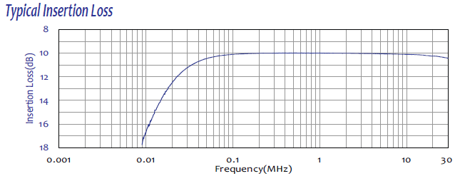
| Insertion Loss | < 17 dB to < 11 dB (9 kHz – 150 kHz, decreasing linearly with log of frequency); < 11 dB (150 kHz – 30 MHz) |
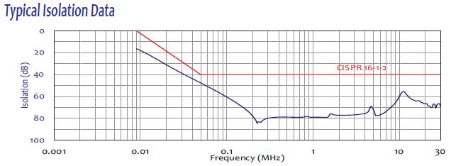
| Isolation | > 0 dB to > 40 dB (9 kHz – 50 kHz, increasing linearly with log of frequency); > 40 dB (50 kHz – 30 MHz) |
| Transient Limiter | Built-in, bypassable, with dual 5 dB attenuation pads |
| RF Measurement Port | 50 Ω N-type (female) |
| Remote Interface | RLI V2.0 via fiber optic |
| Local Line Selection | Front-panel push-buttons (L1, L2, L3, N) |
| Power Configurations | Delta (3-wire) and Wye (4-wire) |
| Cooling | Louvered panels + top air outlets (passive) |
| Dimensions (H × W × D) | See product page |
| Weight | 55.6 lbs (25.2 kg) |
| Operating Temperature | 5 °C to 40 °C |
| Calibration | Individual; ISO 17025 accredited available on request |
| Warranty | Three-year standard warranty |
All values are typical, unless specified. All specifications subject to change without notice.
🔍 Not Sure This Is The Right LISN?
Compare all 25 Com-Power LISN models side-by-side with our interactive selection tool. Filter by current, voltage, frequency, and standards to find your perfect match.
Compare All LISN Models →LI-3P-216 V2.0 Three-Phase V-AMN LISN FAQs
What is the LI-3P-216 and how does its V-AMN network topology differ from a standard 50 μH LISN?
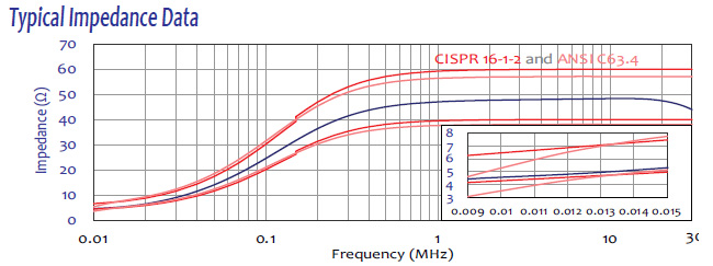
The LI-3P-216 is a four-conductor, 50Ω, 50/250 μH +5Ω three-phase Line Impedance Stabilization Network (LISN), also classified as an Artificial Mains V-Network (V-AMN). Unlike the simpler 50 μH LISN used in the LI-3P-1x series, the V-AMN adds a 5Ω series resistance element and a dual-inductance topology. This makes the LI-3P-216 compliant with the V-network impedance characteristic defined by CISPR 16-1-2 and extends coverage down to 9 kHz, enabling conducted emissions testing across the full sub-150 kHz band that the simpler 50 μH network cannot cover.
What frequency range does the LI-3P-216 cover and why does extending down to 9 kHz matter for modern equipment testing?
The LI-3P-216 operates from 9 kHz to 30 MHz. The extension to 9 kHz is significant because modern power electronics — including variable frequency drives, switch-mode power supplies, solar inverters, and EV charging systems — generate substantial conducted disturbance voltages in the 9 kHz to 150 kHz band. This range is addressed by CISPR 16-1-2 V-network requirements and is increasingly referenced in product standards such as EN 55011 and IEC 61000-3-8 for industrial and medical equipment.
Which EMC compliance standards does the LI-3P-216 satisfy?
The LI-3P-216 is fully compliant with CISPR 16-1-2 for CE marking and ANSI C63.4 for FCC testing. It also supports AS/NZS, VCCI, ISED Canada, and other international frameworks that reference CISPR 16-1-2 V-network measurement methodology.
What does the 50/250 μH +5Ω V-AMN impedance characteristic mean and why is it defined this way?
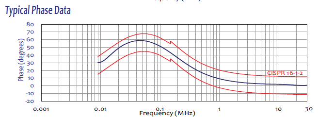
The V-AMN characteristic presents low impedance at power frequency to pass load current freely, while presenting a defined, frequency-dependent impedance to RF disturbance voltages across 9 kHz to 30 MHz. The dual 50/250 μH inductance and 5Ω series resistance produce the impedance versus frequency curve required by CISPR 16-1-2, approximating the mains port impedance seen at the input of equipment in a typical installation. Air-core inductors ensure this profile stays stable regardless of current or temperature.
What three-phase power configurations does the LI-3P-216 support?
The four-conductor network covers Line 1, Line 2, Line 3, and Neutral, making it compatible with both three-phase Delta and three-phase Wye configurations without any internal reconfiguration.
How does the LI-3P-216 remote line switching system work and why is it essential for conducted emissions testing?
The RLI V2.0 Remote LISN Interface switches the measured line between L1, L2, L3, and Neutral via a fiber optic connection. This allows the operator or automated test software to sequentially measure each conductor without re-entering the shielded room or disturbing the EUT. The fiber optic link provides complete galvanic isolation, preventing the control interface from introducing ground loops or RF interference into the measurement path.
How does the transient limiter on the LI-3P-216 differ from those on the LI-3P-1x series, and what does the bypass capability enable?
The LI-3P-216 transient limiter includes two integrated 5 dB attenuation and impedance matching pads plus low-pass and high-pass filter sections, offering more comprehensive receiver protection. Uniquely, it can be bypassed entirely from the front panel or remotely via the RLI V2.0. Bypass mode allows engineers to connect calibrated external limiters, perform raw disturbance voltage diagnostics, or accommodate measurement scenarios where standard limiter attenuation is not desired.
What insertion loss and isolation performance does the LI-3P-216 provide across its full frequency range?
Insertion loss decreases from less than 17 dB at 9 kHz to less than 11 dB at 150 kHz, then remains below 11 dB from 150 kHz to 30 MHz. Isolation increases from greater than 0 dB at 9 kHz to greater than 40 dB at 50 kHz, then exceeds 40 dB through 30 MHz. This graduated profile is characteristic of the V-AMN topology and is within CISPR 16-1-2 specification.
What EUT voltage and current ratings does the LI-3P-216 support?
The LI-3P-216 supports 16 A per phase continuous, 865 V RMS line-to-line, 500 V RMS line-to-ground, and 600 V DC maximum. This accommodates three-phase equipment on standard 230/400 V or 277/480 V industrial supply systems within the 16 A current class.
How does a typical conducted emissions test setup using the LI-3P-216 look in a real EMC laboratory?
The LI-3P-216 is positioned on a conductive ground plane inside a shielded room or semi-anechoic chamber, bonded directly to the plane. The facility three-phase supply connects to the mains input port; the EUT connects to the EUT output port using the color-coded connectors. A 50Ω N-Type coaxial cable runs from the RF measurement port to the EMI receiver. The RLI V2.0 fiber optic cable exits the chamber through a waveguide penetration to the operator station. The engineer then runs sequential 9 kHz to 30 MHz sweeps on L1, L2, L3, and Neutral without entering the room, with the EUT remaining powered throughout.
In what real-world product categories is the LI-3P-216 most commonly required?
The LI-3P-216 is most commonly required when testing three-phase switch-mode power supplies, three-phase input LED drivers, small variable frequency drives for HVAC and pumping, three-phase EV supply equipment (EVSE) up to 16 A per phase, solar micro-inverters with three-phase grid connections, and UPS systems with three-phase input. It is the appropriate choice whenever a product standard requires a V-network measurement method rather than a basic 50 μH network.
How does the LI-3P-216 compare to the LI-3P-116 when selecting a LISN for a new three-phase test program?
The LI-3P-116 uses a standard 50 μH network from 150 kHz to 30 MHz and is appropriate when the product standard only requires a basic 50 μH LISN. The LI-3P-216 uses the V-AMN 50/250 μH +5Ω network from 9 kHz to 30 MHz, includes a bypassable transient limiter with 5 dB pads, and is required when the standard mandates a V-network method or when the EUT generates significant disturbance content below 150 kHz. Engineers should confirm which LISN type the applicable product standard references before selecting.
What industries are driving demand for sub-150 kHz conducted emissions testing with a V-AMN LISN?
The 9 kHz lower limit is most relevant for renewable energy (solar inverters, wind converters), EV and EVSE charging infrastructure, industrial variable frequency drives with low switching frequencies, UPS systems, and power quality conditioning equipment. European regulatory bodies are progressively extending conducted emissions limits below 150 kHz for these categories, making a V-AMN capable LISN essential for forward-looking compliance programs.
Why must the LI-3P-216 mounting plate be connected to earth ground and how should this be done?
The mounting plate is left unpainted to ensure a direct, low-impedance metal-to-metal bond with the conductive ground plane. Three-phase leakage currents must return to earth through the LISN chassis. Without a proper earth bond, these currents create a floating reference that corrupts disturbance voltage measurements and can pose a shock hazard. The ground bond must be established before connecting the mains supply.
How is the LI-3P-216 calibrated and what documentation is provided?
Every LI-3P-216 is individually calibrated per CISPR 16-1-2 and ANSI C63.4. A full calibration data package covering impedance, phase, isolation, and insertion loss versus frequency is included with each unit along with a certificate of calibration. ISO 17025 accredited calibration is available upon request for laboratories under formal accreditation bodies such as A2LA, NVLAP, or UKAS.
What cooling system does the LI-3P-216 use and what is its operating temperature range?
The LI-3P-216 uses passive convection cooling through louvered side panels and four 4-inch square mesh-protected air outlets on the top cover. No forced-air fans are required at 16 A. The operating temperature range is 40°F to 104°F (5°C to 40°C). Top cover outlets must remain unobstructed when the unit is installed in a test enclosure.
What connector ratings and types are used on the LI-3P-216 and what optional accessories are available?
The LI-3P-216 uses color-coded 25A rated receptacle and plug connectors on both the mains input and EUT output ports, with five positions for L1, L2, L3, Neutral, and Protective Earth. The RF measurement port uses a 50Ω N-Type female connector. Optional coaxial adapters (LI-3P-XXXX-ADA with LI-3P-ADA_PP25A plug pin or LI-3P-ADA_PS25A plug socket) are available for non-standard cable configurations.
How is the LI-3P-216 used in a real-world pre-compliance lab for a three-phase LED driver system with a V-network requirement?
For a three-phase LED driver where the product standard requires a V-network measurement, an engineer sets up the LI-3P-216 on a conductive ground plane, connects the driver's three-phase input, and runs pre-compliance sweeps from 9 kHz to 30 MHz using a spectrum analyzer. Because the LED driver's switching frequency and harmonics often fall in the 20 kHz to 150 kHz range — only accessible with the V-AMN network — the LI-3P-216 reveals non-compliances that a 150 kHz-starting LISN would miss entirely. The engineer can then add or tune differential-mode and common-mode EMI filters on the input stage and re-measure iteratively before investing in a formal accredited test.
What does a typical V-network conducted emissions test session look like for a 16 A three-phase EV charging station using the LI-3P-216?
For a 16 A per phase three-phase EV charging station — such as a Type 2 AC charger at 11 kW — the LI-3P-216 connects between the facility supply and the charger's power input in a shielded room, with an EV or EV simulator providing a realistic charging load. With the charger actively delivering power, the RLI V2.0 remote interface is used to sweep L1, L2, L3, and Neutral sequentially from 9 kHz to 30 MHz. The 9 kHz starting frequency is essential because the charger's switching converter typically operates at 20 kHz to 40 kHz, placing its fundamental and early harmonics squarely in the 9 kHz to 150 kHz band that CISPR 16-1-2 V-network testing covers.
How is the LI-3P-216 used during solar inverter type testing at an accredited EMC laboratory?
At an accredited EMC laboratory, the LI-3P-216 is permanently installed in the shielded test room. The three-phase solar inverter EUT connects to the LISN EUT port, and a DC power supply or solar simulator feeds the inverter's DC input while a grid-tie load simulates the AC distribution. The inverter operates at 100 percent of rated output power, and the accredited engineer runs formal quasi-peak and average sweeps from 9 kHz to 30 MHz on each conductor. The LI-3P-216's calibration certificate and individual insertion loss correction data are referenced in the formal test report that supports CE marking.
How does an OEM use the LI-3P-216 during ongoing production quality assurance to ensure conducted emissions compliance is maintained across production batches?
An OEM producing three-phase equipment subject to V-network requirements often installs an LI-3P-216 in a production test area alongside a spectrum analyzer and a simplified pass/fail routine. Each unit from a production batch is scanned from 9 kHz to 30 MHz on a spot-frequency or full-sweep basis with a pre-determined margin below the applicable limit. Units failing this check are quarantined for investigation before shipment. This practice catches batch-level process drift — such as component substitution, filter capacitor tolerance shifts, or PCB layout changes — that might push emissions above the limit before the product reaches an end customer or regulatory authority.
What is a typical scenario where a product initially tested with a 150 kHz LISN fails V-network re-testing, and how does the LI-3P-216 reveal the issue?
A common scenario occurs when a three-phase variable frequency drive passed its conducted emissions test using a standard 50 μH LISN starting at 150 kHz, but a regulatory update demands V-network testing from 9 kHz. When re-tested using the LI-3P-216, the sweep reveals significant emission peaks at 25 kHz, 50 kHz, and 75 kHz — the fundamental switching frequency and its harmonics — that were entirely invisible in the previous test. These emissions may exceed the V-network limit by 10 to 20 dB, requiring a common-mode choke and differential-mode filter capacitors at the drive input. The LI-3P-216 is then used iteratively during filter design to confirm each iteration reduces the sub-150 kHz emissions until the product passes from 9 kHz through 30 MHz.
How is the LI-3P-216 used when qualifying a small three-phase solar micro-inverter string for IEC 62109 and CISPR 11 compliance?
Three-phase solar micro-inverters and string inverters rated at up to 11 kW are commonly tested with the LI-3P-216 for IEC 62109 safety and CISPR 11 conducted emissions requirements. The inverter’s DC input is fed from a programmable DC source simulating PV maximum power point conditions, while the LI-3P-216 connects between the facility grid supply and the inverter AC output. V-network sweeps from 9 kHz to 30 MHz on all four conductors capture the switching noise from the DC-AC conversion stages, directly supporting CE marking required for sale in the EU and satisfying relevant grid connection code emissions requirements.
What is a typical scenario where the LI-3P-216 is used at an industrial automation OEM to check a new VFD variant’s conducted emissions before a product launch?
When an OEM releases a new variant of a certified VFD — such as a version with updated IGBT modules or revised gate drive firmware — the existing certification may not automatically cover it. The EMC engineer uses the LI-3P-216 to perform a delta measurement, comparing V-network emissions of the new variant against the certified version from 9 kHz to 30 MHz on all four conductors. If no increase is found, the engineer documents the equivalence in the product technical file to support a declaration of conformity without a full re-certification. If any increase appears, particularly in the 9 kHz to 150 kHz sub-band, it can be resolved before the product launch date.
How is the LI-3P-216 used in a university or research institution’s power electronics laboratory for conducted emissions characterization of experimental converter topologies?
University and research institution power electronics laboratories use the LI-3P-216 to characterize conducted emissions of experimental topologies such as matrix converters, multi-level inverters, and wide-bandgap semiconductor-based drives. The V-AMN network starting at 9 kHz is essential for research converters because wide-bandgap designs often switch at 100 kHz or higher, with switching harmonics falling well within the 9 kHz to 150 kHz sub-band. The LI-3P-216 provides a standardized measurement reference that allows research results to be compared across institutions and related directly to commercial product compliance limits.

Quote Request
Other EMC Test Equipment
- Absorbing Clamps
- Antenna Kits
- Antenna Masts - Automated and Manual
- Antennas
- Bulk Current Injection probes
- CDNs - Coupling Decoupling Network
- Comb Generators
- Conducted Immunity Test Systems
- Current Monitor Probes
- Current Probe Calibration Fixtures
- EM Clamps
- Feed Through Capacitor
- ISNs - Impedance Stabilization Network
- LISNs - Single Phase
- LISNs - TEMPEST
- LISNs - Three Phase
- Magnetic Field Generator
- Near Field Probes
- Power Amplifiers
- Pre-compliance Emissions Test Systems
- Preamplifiers
- Spectrum Analyzers
- Surge Generators
- System Controllers
- Transient Limiters
- Tripods For EMC
- Turntables