
32 Amps Three-Phase Line Impedance Stabilization Network
- Provides CISPR-compliant 50/250 µH +5Ω network for stable three-phase conducted EMI testing.
- Supports 9 kHz–30 MHz performance with consistent impedance and high isolation accuracy.
- Handles up to 32A per line, ideal for medium-power commercial and industrial three-phase EUTs.
- Offers remote or local line switching for safe, repeatable EMI receiver connection control.
- Uses air-core inductors to prevent saturation and ensure reliable results under varying loads.
- Ideal for compliance testing to CISPR 16-1-2 and ANSI C63.4 for commercial EMC applications.
- Useful in labs evaluating drives, UPS units, controls, and power-conversion equipment.
- Supports real-world EMC approval workflows by ensuring accurate disturbance-voltage capture.
- Includes NIST-traceable calibration for impedance, phase, isolation, and insertion loss.
- ISO 17025 accredited calibration available on request for formal compliance requirements.
-
Frequency range: 9 kHz to 30 MHz for conducted emissions compliance
-
32 A maximum continuous current per line
-
Compliant with CISPR 16-1-2 and ANSI C63.4
-
Four-conductor 50 Ω, 50/250 µH +5 Ω network for Delta and Wye systems
-
Remote or local line switching of L1, L2, L3, N via RLI-100
-
Built-in transient limiter with attenuation and filtering for instrument protection
-
Air-core inductors for saturation-free performance
-
Unpainted mounting plates for proper grounding and low-impedance bonding
-
50 Ω N-type measurement port
-
Three-year standard warranty
General
-
Product Type: Line Impedance Stabilization Network (LISN)
-
Application: Power-line conducted emissions testing
-
Standards: CISPR 16-1-2 (CE), ANSI C63.4 (FCC)
-
Network Type: 50 Ω, 50/250 µH +5 Ω, 4-conductor
-
Frequency Range: 9 kHz to 30 MHz
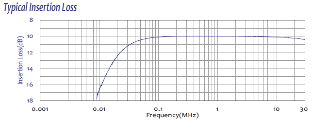
Insertion Loss
-
9 kHz–150 kHz: <17 dB to <11 dB (decreasing with log frequency)
-
150 kHz–30 MHz: <11 dB
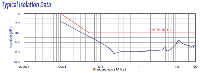
Isolation
-
9 kHz–50 kHz: >0 dB to >40 dB (increasing with log frequency)
-
50 kHz–30 MHz: >40 dB
EUT Input Power Ratings
-
Maximum Current: 32 A continuous per line
-
Max AC Voltage: 865 V rms line-to-line, 500 V rms line-to-ground
-
Max DC Voltage: 600 V DC
Electrical / Connectors
-
Power Input Plug (attached): 32A receptacle pins (Red, Yellow, Blue, Black, Green)
-
Power Input Socket: 32A plug sockets
-
Power Output Socket: 32A receptacle sockets
-
Power Output Plug: 32A plug pins
-
RF Measurement Port: 50 Ω N-type (female)
-
Fiber Optic Ports: Avago duplex POF jack
-
Remote Interface Power: 6 V DC, 500 mA (unregulated)
Environmental / Cooling
-
Operating Temperature: 5 °C to 40 °C (40 °F to 104 °F)
-
Cooling: Louvered side panels (no forced air)
Product Weight
- Weight: 59.1 lbs (26.8 kg)
| Title | Link |
|---|---|
| LI-3P-232 Datasheet | View PDF |
🔍 Not Sure This Is The Right LISN?
Compare all 25 Com-Power LISN models side-by-side with our interactive selection tool. Filter by current, voltage, frequency, and standards to find your perfect match.
Compare All LISN Models →LI-3P-232 V2.0 Three-Phase V-AMN LISN FAQs
What is the LI-3P-232 and which medium-power industrial equipment class does it support?
The LI-3P-232 is a four-conductor, 50Ω, 50/250 μH +5Ω three-phase Line Impedance Stabilization Network (LISN), also known as an Artificial Mains V-Network (V-AMN), rated at 32 amperes per phase. It is designed for power line conducted emissions compliance testing of medium-power three-phase industrial equipment — including variable frequency drives, three-phase EV charging stations, and industrial automation controllers — that require both the V-network impedance characteristic and a higher current rating than the 16 A LI-3P-216.
What frequency range does the LI-3P-232 cover and what is the significance of the 9 kHz lower limit?
The LI-3P-232 operates from 9 kHz to 30 MHz. The 9 kHz lower limit is essential for testing power conversion equipment that generates conducted disturbances below the traditional 150 kHz CISPR band. Variable frequency drives, solar inverters, and EV chargers can all produce harmonic and switching noise that must be measured starting from 9 kHz when product standards reference CISPR 16-1-2 V-network requirements.
What EMC standards does the LI-3P-232 comply with?
The LI-3P-232 is fully compliant with CISPR 16-1-2 for CE marking and ANSI C63.4 for FCC testing. It also supports AS/NZS, VCCI, ISED Canada, and other international frameworks adopting equivalent V-network conducted emissions measurement methodologies.
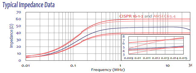
Why does the LI-3P-232 use a 50/250 μH +5Ω V-AMN network rather than a simple 50 μH network?
The 50 μH network is specified for measurements from 150 kHz to 30 MHz. The V-AMN 50/250 μH +5Ω topology is required when measurements must extend down to 9 kHz, producing the specific frequency-dependent impedance defined by CISPR 16-1-2 for the V-network method. For medium-power three-phase equipment increasingly regulated below 150 kHz, the V-AMN is the correct measurement network.
What three-phase wiring configurations can the LI-3P-232 accommodate?
The four-conductor network supports both three-phase Delta and three-phase Wye configurations via conductors for Line 1, Line 2, Line 3, and Neutral, interfacing directly with a wide range of industrial power distribution systems including those with and without neutral conductors.
How does the LI-3P-232 remote switching system enable automated and semi-automated EMC test sequences?
The RLI V2.0 Remote LISN Interface communicates with the LI-3P-232 over a 10-meter fiber optic cable, allowing the operator or test automation software to select L1, L2, L3, or Neutral from outside the shielded enclosure. This eliminates repeated chamber entry and allows the entire four-conductor test sequence to run as a single automated sweep. Fiber optic isolation prevents any control-path interference from reaching the RF measurement circuit.
What does the bypassable transient limiter on the LI-3P-232 provide and when should bypass mode be used?
The Transient Limiter incorporates two 5 dB attenuation and impedance matching pads plus low-pass and high-pass filter sections, protecting the EMI receiver from switching transients. It can be bypassed from the front panel or remotely via the RLI V2.0. Bypass is useful for raw disturbance voltage diagnostics, measurement chain calibration, or when a specific standard specifies no limiter attenuation at the measurement port.
What insertion loss and isolation does the LI-3P-232 achieve across 9 kHz to 30 MHz?
Insertion loss ranges from less than 17 dB at 9 kHz, decreasing logarithmically to less than 11 dB at 150 kHz, then stays below 11 dB through 30 MHz. Isolation increases from greater than 0 dB at 9 kHz to greater than 40 dB at 50 kHz, then exceeds 40 dB through 30 MHz — meeting CISPR 16-1-2 requirements across the complete band.
What are the maximum EUT power ratings for equipment connected to the LI-3P-232?
The LI-3P-232 supports 32 A per phase continuous, 865 V RMS line-to-line, 500 V RMS line-to-ground, and 600 V DC. On a 400 V three-phase Wye supply, 32 A corresponds to approximately 22 kVA of apparent power, covering a broad range of commercial and industrial three-phase equipment.
How does a typical real-world EMC test setup with the LI-3P-232 differ from using a 16 A LISN?
The physical setup is essentially the same: the LI-3P-232 is bonded to a conductive ground plane, the mains supply connects to the input port, the EUT connects to the EUT output port, and the RF measurement port feeds the EMI receiver. The key difference is that 50A rated connectors accommodate the larger power cables required for 32 A operation. For EUT types such as 22 kW three-phase drives or industrial chillers, the LI-3P-232 provides the current headroom while maintaining the V-AMN impedance conditions required by the product standard.
In which industrial test scenarios is the LI-3P-232 the correct LISN choice over the LI-3P-216?
The LI-3P-232 is required when the EUT draws between 17 and 32 amperes per phase and the product standard mandates V-network measurements to 9 kHz. Typical applications include mid-range VFDs for compressor and pump systems, three-phase EV charging stations in the 11 kW to 22 kW range, commercial HVAC drive systems, industrial welding power sources, and multi-axis servo amplifiers.
Why are air-core inductors critical for accurate V-AMN measurements at 32 A?
Air-core inductors maintain constant permeability regardless of current, temperature, or frequency. At 32 A, ferrite or steel-core inductors would saturate and alter their inductance value, pulling the V-AMN impedance characteristic out of CISPR 16-1-2 tolerance. Air-core construction guarantees the 50/250 μH +5Ω network impedance remains accurate at full rated current, keeping all measurements valid for compliance purposes.
What grounding and installation requirements apply to the LI-3P-232?
The mounting plate is left unpainted for direct metal-to-metal bonding to the conductive ground plane or test table. At 32 A, leakage currents can be significant, making a low-impedance earth bond essential for both measurement validity and personnel safety. In facilities where the ground plane is painted or coated, a dedicated bonding strap to the chassis mounting holes should be used.
What connector types and current ratings are used on the LI-3P-232 power ports?
The LI-3P-232 uses color-coded 50A rated receptacle and plug connectors on both the mains input and EUT output ports, with five positions for L1, L2, L3, Neutral, and Protective Earth. The RF measurement port uses a 50Ω N-Type female connector. Optional coaxial adapters (LI-3P-XXXX-ADA with LI-3P-ADA_PP50A or LI-3P-ADA_PS50A) are available for non-standard cable arrangements.
How is the LI-3P-232 calibrated and what documentation accompanies each unit?
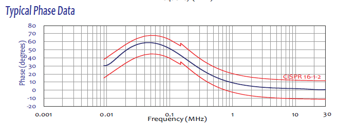
Every LI-3P-232 is individually calibrated per CISPR 16-1-2 and ANSI C63.4. Calibration data covering impedance, phase, isolation, and insertion loss versus frequency across the full 9 kHz to 30 MHz range is supplied with each unit along with a certificate of calibration. ISO 17025 accredited calibration is available upon request for formally accredited laboratories.
What cooling design does the LI-3P-232 use and what are the operating temperature limits?
The LI-3P-232 uses passive convection cooling through louvered side panels and four 4-inch square mesh-protected air outlets on the top cover, without forced-air fans. The operating range is 40°F to 104°F (5°C to 40°C). Adequate clearance around the top cover outlets is important in warm test environments to prevent thermal buildup at the 32 A continuous rating.
How does the LI-3P-232 fit into a broader EMC testing strategy when a product family spans multiple current ratings?
In a laboratory testing multiple three-phase product variants at different power ratings, the LI-3P-232 covers variants up to 32 A per phase, the LI-3P-263 covers up to 63 A, and the LI-3P-2100 covers up to 100 A. Since all LI-3P-2x models share the same V-AMN topology, frequency range, and CISPR 16-1-2 compliance, test procedures remain identical across the product family and results are directly comparable — making the series a scalable solution for laboratories testing a wide range of industrial three-phase equipment.
How is the LI-3P-232 used when testing a 22 kW three-phase EV charging station for CE marking in an accredited laboratory?
A 22 kW three-phase AC EV charging station draws approximately 32 A per phase from a 400 V Wye supply — exactly the LI-3P-232's rated capacity. In an accredited laboratory, the charger connects to the LISN EUT output port with an EV or EV load simulator providing a realistic charging load. With the charger delivering at or near rated 22 kW output, the RLI V2.0 remote interface enables sequential 9 kHz to 30 MHz sweeps on L1, L2, L3, and Neutral. Formal quasi-peak and average results, corrected for LI-3P-232 insertion loss, are compiled into the CE marking test report submitted to the notified body. Because EV chargers are increasingly subject to standards requiring V-network testing below 150 kHz, the V-AMN network of the LI-3P-232 is mandatory for this test category.
How do industrial automation system integrators use the LI-3P-232 during factory acceptance testing of variable frequency drives?
Industrial automation system integrators performing factory acceptance testing (FAT) of VFDs rated at 18 to 30 A per phase use the LI-3P-232 between the factory mains and the VFD power input. The VFD operates at rated load using an appropriate motor, and conducted emissions sweeps from 9 kHz to 30 MHz are performed on each phase and neutral. FAT results confirm the VFD meets the applicable standard — typically EN 61800-3 for variable-speed drives — in its final shipped configuration with its standard EMI filter installed. This prevents the scenario where a VFD that passed testing with a laboratory prototype filter arrives at the customer site with a different production filter version that does not achieve the same suppression.
What is a real-world use case for the LI-3P-232 in testing commercial HVAC drive systems at a test laboratory?
Commercial HVAC variable-speed drives for large chiller compressors and air handling units commonly operate at 15 to 30 A per phase on a 400 V or 480 V supply. The LI-3P-232 connects between the lab supply and the HVAC drive EUT with a representative motor or dynamometer load. Product standards for HVAC drives often reference CISPR 16-1-2 V-network requirements, making the LI-3P-232 mandatory over a simpler 50 μH LISN. The engineer records sweeps at multiple drive speeds since the switching harmonics of the VFD shift with operating frequency — worst-case emissions may occur at a specific speed point rather than at rated speed.
How is the LI-3P-232 applied during EMC re-qualification after a design change to an existing three-phase product?
When a manufacturer modifies a certified three-phase product — changing an EMI filter component, updating power switch technology, or revising the PCB layout — the product's conducted emissions certification may require re-qualification. For products drawing up to 32 A per phase, the LI-3P-232 measures the modified product's V-network profile and compares it to the original certification data. If the change was a controlled improvement, the LI-3P-232 measurements confirm and document it for the regulatory file. If the change unintentionally increased emissions, the measurements identify which frequency ranges were affected, guiding corrective action before formal re-certification.
How is the LI-3P-232 used to support multi-market certification of a three-phase industrial product requiring compliance with FCC, CE, and VCCI simultaneously?
A three-phase industrial product targeting simultaneous market entry in the US, EU, and Japan requires compliance with FCC (referencing ANSI C63.4), CISPR 16-1-2 (for CE marking), and VCCI — all referencing V-network or equivalent measurement methods. A single set of V-network sweeps from 9 kHz to 30 MHz with the LI-3P-232 allows comparison against all three regulatory limit sets in a single test event. Because ANSI C63.4 and CISPR 16-1-2 V-network limits are harmonized in the overlapping range, and VCCI adopts CISPR limits, a single LI-3P-232 data set is often sufficient to support tri-market certification documentation for products up to 32 A per phase.
How is the LI-3P-232 used in a test laboratory qualifying a 30 kW three-phase grid-tie inverter for IEC 61727 and CISPR 11 compliance?
A 30 kW three-phase grid-tie inverter for commercial rooftop solar draws approximately 32 A per phase on a 400 V supply at rated output. The LI-3P-232 connects between the facility supply and the inverter AC port while a high-current DC source simulates the PV array at maximum power point. V-network sweeps from 9 kHz to 30 MHz on all four conductors capture the MPPT and DC-AC conversion switching harmonics. This combined approach with the LI-3P-232 supports both the grid connection approval and CE marking test report in a single test configuration.
What is a real-world use case for the LI-3P-232 when performing V-network conducted emissions testing on medical imaging support equipment?
Three-phase chiller systems and power conditioning units for MRI and CT scanners drawing 20 to 32 A per phase must meet IEC 60601-1-2 EMC requirements including conducted emissions testing. At an accredited medical EMC laboratory, the LI-3P-232 performs V-network sweeps from 9 kHz to 30 MHz against the most stringent CISPR 11 Class B limits applicable to medical electrical equipment. The V-AMN network starting at 9 kHz captures sub-150 kHz emissions particularly important for medical equipment because interference in this range can couple into patient monitoring and diagnostic systems.
How is the LI-3P-232 used when an EMC engineer investigates why a 22 kW three-phase VFD fails conducted emissions after installation in a customer’s application-specific enclosure?
A VFD that passed its standalone conducted emissions certification may fail when integrated into a customer-specific enclosure with additional cabling, a transformer, or a power distribution assembly. The LI-3P-232 measures V-network conducted emissions of the complete integrated system from 9 kHz to 30 MHz and compares results to the standalone certified data. Common causes include cable routing that adds inductive coupling between drive output and input cables, ground loop paths through enclosure metalwork, or resonance between the drive’s input EMI filter and the added supply transformer. Measurements on all four conductors allow the engineer to localize the problem to specific conductors and frequency ranges, guiding targeted modifications.

Quote Request
Other EMC Test Equipment
- Absorbing Clamps
- Antenna Kits
- Antenna Masts - Automated and Manual
- Antennas
- Bulk Current Injection probes
- CDNs - Coupling Decoupling Network
- Comb Generators
- Conducted Immunity Test Systems
- Current Monitor Probes
- Current Probe Calibration Fixtures
- EM Clamps
- Feed Through Capacitor
- ISNs - Impedance Stabilization Network
- LISNs - Single Phase
- LISNs - TEMPEST
- LISNs - Three Phase
- Magnetic Field Generator
- Near Field Probes
- Power Amplifiers
- Pre-compliance Emissions Test Systems
- Preamplifiers
- Spectrum Analyzers
- Surge Generators
- System Controllers
- Transient Limiters
- Tripods For EMC
- Turntables