
LISN 25 Amps for MIL-STD 461
- The LI-400C Line Impedance Stabilization Network provides the necessary measurement platform for performing power line conducted emissions compliance testing as required by most worldwide standards for commercial products.
- The LI-400C is compliant with MIL-STD 461. The LISN provides defined stable impedance and isolates the EUT from power source influences, thereby providing accurate and repeatable results.
- The LI-400C includes one pair of, separately housed, single-conductor networks, to be installed in series with each current-carrying conductor in a single-phase, dual-phase, or DC power system.
- A second LI-400C pair can be used to accommodate 3-phase power systems (Wye or Delta configurations). The LI-400C is equipped with Superior Electric SUPERCON® shrouded sockets at the mains (power input) and EUT (power output) ports.
- The matching color-coded plugs for connection to the mains and EUT wiring are included. This LISN uses air-core inductors to prevent saturation and permeability variation.
- The mounting plate of the LI-400C is left unpainted in order to facilitate connection to earth ground in its installation, which is essential due to high leakage current.
- Use of a Transient Limiter for impedance matching, reduction of out-of-band emissions and transient protection for your measurement instrument is highly recommended and available from Com- Power.
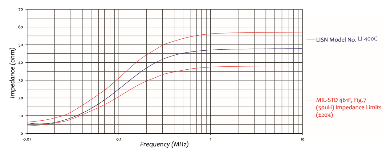
- All Com-Power LISNs are individually calibrated in compliance with the relevant requirements of MIL-STD 461. Impedance and Insertion Loss data is supplied with each unit, along with the calibration certificate.
- Frequency range of 10 kHz to 10 MHz
- Fully compliant with MIL-STD 461
- “Air-core” inductors to prevent saturation
- Individual Calibration Included
- Three-Year Warranty
- Product Name: Line Impedance Stabilization Network (LISN)
- Specification: MIL-STD 461
- Application: Power Line conducted emission tests
- Frequency Range: 10KHz - 10 MHz
- RF Connector: 50 Ohms N-type (female)
- Current Rating: 25 Amp
- Voltage Rating: 270 VAC (Line to Ground) 50/60 Hz, 135 VAC (Line to Ground) 400 Hz, 380 VDC
- Inductors: 50 microhenry (air-core)
- Mains & EUT Connections: Superior Electric SUPERCON Shrouded sockets
- Dimensions (each network): 13 x 7 x 7 inches / 33 x 17.7 x 17.7 cm
- Weight (each network): 14 lbs / 6.3 kg
🔍 Not Sure This Is The Right LISN?
Compare all 25 Com-Power LISN models side-by-side with our interactive selection tool. Filter by current, voltage, frequency, and standards to find your perfect match.
Compare All LISN Models →LI-400C MIL-STD-461 Single-Phase LISN FAQs
What is the LI-400C and what type of testing is it designed for?
The LI-400C is a single-conductor, 50Ω, 50 μH Line Impedance Stabilization Network (LISN) designed for power-line conducted emissions compliance testing per MIL-STD-461 at currents up to 25 amperes. It implements the MIL-STD-461 50 μH LISN network configuration (Figure 7) used in CE102 conducted emissions testing, accommodating multiple military power system frequencies and voltages including 50/60 Hz ground facility power, 400 Hz aircraft and shipboard power, and military DC bus systems.
What standard does the LI-400C comply with and what CE test does it support?
The LI-400C is compliant with MIL-STD-461 and supports CE102 (10 kHz to 10 MHz) conducted emissions testing using the 50 μH LISN network specified in MIL-STD-461 Figure 7. It is not designed for CISPR 16-1-2 or ANSI C63.4 commercial testing, and should not substitute for the 50 μH V-network LISNs used in commercial compliance, as the network topologies and impedance characteristics differ between the MIL-STD-461 and CISPR configurations.
What is the frequency range of the LI-400C and how does it compare to other military LISNs?
The LI-400C covers 10 kHz to 10 MHz — the CE102 frequency range defined by MIL-STD-461. This is narrower than the LI-325C and LI-350 (10 kHz to 400 MHz, 5 μH network). For MIL-STD-461 programs requiring coverage above 10 MHz or for DO-160 testing, the LI-325C or LI-350 with their 5 μH networks should be used.
Why does the LI-400C use a 50 μH inductor when the LI-325C and LI-350 use 5 μH for MIL-STD-461 testing?
MIL-STD-461 specifies both a 5 μH and a 50 μH LISN configuration for CE102, depending on the test method and equipment category. The LI-400C implements the 50 μH MIL-STD-461 Figure 7 configuration. This is distinct from the CISPR 16-1-2 50 μH V-network — component values, internal topology, and impedance characteristics differ. The test engineer must check the specific MIL-STD-461 test plan and contract requirements to determine whether the 5 μH (LI-325C/LI-350) or the 50 μH MIL-STD-461 (LI-400C/LI-4100) LISN is required.
What is the current rating of the LI-400C and what class of military equipment does it support?
The LI-400C is rated at 25 amperes. This supports military vehicle electronic control units, shipboard instrument systems, military sensor and radar signal processing units, communication transceivers and amplifiers, navigation and fire control systems, ground-based communication and intelligence equipment, and military support equipment — essentially any military electronic subsystem not involving high-power transmitters, drive systems, or power conversion equipment drawing more than 25 A.
What are the voltage ratings of the LI-400C and what military power systems does it accommodate?
The LI-400C is rated at 270 VAC line-to-ground at 50/60 Hz, 135 VAC line-to-ground at 400 Hz, and 380 VDC. This covers 120 VAC 60 Hz military ground facilities, 240 VAC 60 Hz split-phase power, 115 VAC 400 Hz aircraft and shipboard power, and 28 VDC, 48 VDC, 270 VDC, and 380 VDC military DC bus systems.
The LI-400C is sold as a pair. Why is a pair required and how are they connected?
CE102 testing requires a LISN in series with each current-carrying conductor simultaneously. One LI-400C is installed in the Line conductor and one in the Neutral (or positive/negative DC). Measurements are performed one conductor at a time; the inactive RF port is terminated at 50 Ω. For three-phase military systems, a second LI-400C pair accommodates Phase B, Phase C, and Neutral.
What type of connectors does the LI-400C use at the mains and EUT ports?
The LI-400C uses Superior Electric SUPERCON® shrouded sockets at both mains and EUT ports, with color-coded plugs included. The shrouded design protects against accidental contact with live conductors, and color coding prevents polarity errors during connection.
Why is the mounting plate of the LI-400C left unpainted and what grounding is required?
The unpainted mounting plate enables a low-impedance metal-to-metal bond to the MIL-STD-461 reference bonding plane. LISN internal capacitors create leakage current paths between power line conductors and the chassis that must return to the bonding plane. Without a verified low-impedance bond, both CE102 measurement accuracy and personnel safety are compromised.
What RF connector does the LI-400C use and what should be connected to the RF measurement port?
The LI-400C uses a 50 Ω N-type female RF connector, connecting via 50 Ω coaxial cable to an EMI receiver configured for CE102 scanning from 10 kHz to 10 MHz. The inactive LISN RF port must be terminated at 50 Ω. Com-Power recommends a Transient Limiter for impedance matching, out-of-band attenuation, and receiver transient protection.
What insertion loss does the LI-400C provide and how is it applied in CE102 post-processing?
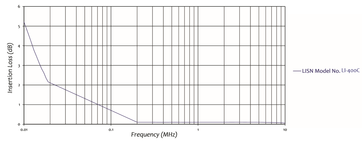
Insertion loss data across 10 kHz to 10 MHz is supplied in the individual unit calibration documentation. The frequency-specific insertion loss correction from calibration data must be added to raw receiver readings at each frequency point to obtain actual disturbance voltages, compared against MIL-STD-461 CE102 limits. The 50 μH insertion loss at the low end of the CE102 range (10 kHz to 150 kHz) is significant and the per-frequency calibration correction is essential for accurate results.
How is the LI-400C individually calibrated and what calibration data is supplied?
Every LI-400C is individually calibrated per MIL-STD-461. Impedance and insertion loss data across 10 kHz to 10 MHz are supplied with a certificate of calibration, verifying the impedance characteristic against MIL-STD-461 tolerance limits and providing frequency-dependent insertion loss corrections.
What is the warranty coverage for the LI-400C?
The LI-400C carries a three-year warranty from Com-Power Corporation. Periodic recalibration on a one- or two-year interval is recommended to maintain traceability for MIL-STD-461 CE102 compliance programs.
What are the physical dimensions and weight of the LI-400C?
Each LI-400C network measures 15 x 7 x 7 inches (38 x 17.7 x 17.7 cm) and weighs 6 lbs (2.7 kg). A complete single-phase CE102 installation requires space for both units on the MIL-STD-461 bonding plane, with power cable routing to mains and EUT ports and a coaxial cable to the EMI receiver positioned per MIL-STD-461 test setup requirements.
What is a Transient Limiter and why does Com-Power recommend one with the LI-400C?
A Transient Limiter inserted between the LI-400C RF port and the EMI receiver provides impedance matching, attenuates out-of-band emissions below 10 kHz and above 10 MHz, and protects against voltage transients from EUT switching events or military power system disturbances that could damage the sensitive receiver input stage.
How does the LI-400C compare to the LI-325C and LI-350 for MIL-STD-461 testing?
The LI-400C uses a 50 μH MIL-STD-461 network (Figure 7), 10 kHz to 10 MHz. The LI-325C and LI-350 use a 5 μH network, 10 kHz to 400 MHz, and additionally support DO-160. The test engineer must consult the program-specific test plan and contract documentation to determine whether the 5 μH or the 50 μH MIL-STD-461 LISN is required for the program.
How does the LI-400C compare to the LI-4100?
The LI-400C (25 A) and LI-4100 (100 A, forced-air cooling) both use the 50 μH MIL-STD-461 CE102 network covering 10 kHz to 10 MHz. The LI-4100 additionally supports higher voltages: 525 VAC at 50/60 Hz, 270 VAC at 400 Hz, 135 VAC at 800 Hz, and 600 VDC. Choose the LI-400C for military subsystems drawing up to 25 A from standard military power systems. Choose the LI-4100 for equipment drawing up to 100 A or operating from power systems exceeding the LI-400C’s voltage ratings.
What types of equipment cannot be tested with the LI-400C?
The LI-400C is not suitable for: equipment exceeding 25 A (use LI-4100); DO-160 avionics testing (use LI-325C or LI-350); commercial CISPR 16-1-2 / ANSI C63.4 testing (use LI-125C or LI-150C); CISPR 25 automotive testing (use LI-550C); MIL-STD-461 CE102 programs requiring the 5 μH network (use LI-325C or LI-350); or power systems exceeding 270 VAC at 50/60 Hz, 135 VAC at 400 Hz, or 380 VDC (use LI-4100).
How is the LI-400C used in a MIL-STD-461F CE102 test on a military vehicle communication system?
The LI-400C pair is bonded to the MIL-STD-461 reference bonding plane. The vehicle’s 28 VDC supply connects to the mains inputs; the communication system connects to the EUT outputs. An EMI receiver configured for CE102 scanning connects to the Line LISN RF port through a Transient Limiter; the Neutral RF port is terminated at 50 Ω. The system is operated in its worst-case transmit mode, which typically generates higher conducted emissions than receive-only due to the high-power RF output stage’s DC bus demand. Results are compared against MIL-STD-461F CE102 limits for the platform category.
How does an EMC laboratory apply the LI-400C when qualifying a military shipboard electronics unit for CE102 compliance?
Shipboard electronics powered from 115 VAC 400 Hz ship bus power are tested using the LI-400C because its 135 VAC line-to-ground at 400 Hz rating accommodates this power standard. The ship bus simulator supplies 115 VAC 400 Hz at up to 25 A; the shipboard unit operates in normal mode and any high-power worst-case modes. CE102 sweeps from 10 kHz to 10 MHz are compared against MIL-STD-461 CE102 limits for Below Deck Navy platform categories from the applicable MIL-STD-461 revision.
How is the LI-400C used in developmental CE102 testing of a military sensor system during design verification?
During design verification of a military sensor (infrared sensor unit, battlefield radar front-end processor), early CE102 testing with the LI-400C identifies non-compliances before the formal qualification test. The sensor system is tested in all functional modes (initialization, standby, full operation). CE102 sweeps from 10 kHz to 10 MHz are compared against applicable CE102 limits. Early identification of non-compliant bands allows the hardware team to add power line filtering, modify converter switching frequency, or implement EMI reduction measures — reducing schedule risk and qualification test failure probability.
How does an EMC engineer use the LI-400C to investigate CE102 result differences across multiple military power supply configurations?
When a military subsystem’s CE102 results differ across 28 VDC vehicle bus, 115 VAC 60 Hz facility supply, and 115 VAC 400 Hz aircraft power, the LI-400C’s multi-frequency voltage rating (270 VAC 50/60 Hz, 135 VAC 400 Hz, 380 VDC) allows the same LISN pair to be used across all three configurations without changing equipment. CE102 sweeps in each configuration reveal how the EUT’s internal power supply topology interacts with different source impedances and power frequencies — helping determine whether non-compliance is configuration-specific or universal, guiding the choice of filtering approach and selection of the worst-case test configuration for the formal qualification program.


Quote Request
Other EMC Test Equipment
- Absorbing Clamps
- Antenna Kits
- Antenna Masts - Automated and Manual
- Antennas
- Bulk Current Injection probes
- CDNs - Coupling Decoupling Network
- Comb Generators
- Conducted Immunity Test Systems
- Current Monitor Probes
- Current Probe Calibration Fixtures
- EM Clamps
- Feed Through Capacitor
- ISNs - Impedance Stabilization Network
- LISNs - Single Phase
- LISNs - TEMPEST
- LISNs - Three Phase
- Magnetic Field Generator
- Near Field Probes
- Power Amplifiers
- Pre-compliance Emissions Test Systems
- Preamplifiers
- Spectrum Analyzers
- Surge Generators
- System Controllers
- Transient Limiters
- Tripods For EMC
- Turntables