
AH-840 Wideband Horn Antenna (18–40 GHz) for 5G FR2 & EMC Testing
-
The AH-840 is a broadband, linearly polarized double-ridge waveguide horn antenna operating over 18 GHz to 40 GHz.
-
It is suitable for both transmitting and receiving in EMI emissions and immunity testing.
-
The antenna is constructed from high-grade, corrosion-resistant aluminum and painted for additional protection.
-
It features a high-quality 2.92 mm (K-type) coaxial connector for secure and efficient signal transfer.
-
The AH-840 is capable of handling up to 10 watts with the adapter or 200 watts for direct waveguide connection.
-
It can generate field strengths of over 1,000 V/m at 1 meter with 200 watts of input power.
-
The antenna can be used as a substitution antenna for ERP and EIRP measurements of intentional radiators.
-
It complies with regulatory standards including FCC, CE, MIL-STD-461, RTCA DO-160, FDA, and ETSI.
-
Each AH-840 is individually calibrated per ANSI C63.5 with NIST traceability; ISO 17025 calibration is available.
-
It is designed for daily use in indoor or outdoor lab environments, even under harsh weather conditions.
-
The AH-840 supports mounting on a tripod or mast via a standard 1/4-inch x 20 threaded hole.
-
Additional uses include site comparisons, shielding effectiveness testing, field monitoring, and site surveys.
Features
- ▸ Complete 18 GHz to 40 GHz coverage in a single antenna — combines the K-band range of the AH-826 and the Ka-band range of the AH-640 into one antenna; covers all 5G NR FR2 bands (n257, n258, n260, n261), full Ka-band satellite, 24 GHz automotive radar, and 77 GHz radar second harmonic.
- ▸ Lab consolidation in one antenna — eliminates the antenna swap between K-band and Ka-band test phases, the second calibration certificate to manage, and the second antenna to store and transport — ideal for portable rigs, single-operator stations, and capital-conscious labs.
- ▸ Double ridge waveguide design with precisely tuned response — the broadband double ridge geometry maintains usable performance across the full 22 GHz of the band, where simpler horns would have multiple resonant gaps.
- ▸ Up to 200 W direct waveguide / 10 W coaxial — 200 W direct to the waveguide flange enables radiated immunity at field strengths exceeding 1,000 V/m at 1 m; 10 W coaxial mode through the included waveguide-to-coax adapter for emissions and routine immunity work.
- ▸ Removable waveguide-to-coax adapter — choose coaxial drive for instrumentation flexibility or remove the adapter for direct waveguide drive at maximum power and lowest insertion loss.
- ▸ Excellent VSWR (avg 1.42:1) — among the lowest reflected power figures in the lineup, protecting expensive mmWave amplifiers and minimizing measurement error.
- ▸ Isotropic gain 19.1–23.6 dBi (avg 21.9 dBi) — high directional gain across the band reduces amplifier power requirements for a target field strength.
- ▸ 2.92 mm (K-type) coaxial connector — precision RF interface rated to 40 GHz, matching the antenna's full upper frequency. SMA-compatible mechanically but engineered for the entire 18–40 GHz range.
- ▸ Extremely lightweight (1 lb / 0.5 kg) — complete assembly fits within 5.9″ × 8.7″ × 7.9″, easy to set up, position, and transport for portable mmWave testing.
- ▸ High-grade corrosion-resistant aluminum, painted finish — built for daily indoor and outdoor use, even under continuous extreme weather exposure.
- ▸ Standard 1/4″-20 mounting hole — located in the center of the antenna's base plate; mounts on the AT-812 Tripod or any compatible support.
- ▸ Transmit and receive capable — serves as receiving antenna for K/Ka-band emissions and transmitting antenna for radiated immunity in the same band, removing antenna swaps mid-test.
- ▸ ERP / EIRP substitution antenna across full 18–40 GHz — calibrated reference for substitution-method measurements per FCC/TCB and ETSI procedures across the entire mmWave compliance range.
- ▸ Regulatory compliance applications — suitable for FCC Part 15/30, CE, MIL-STD-461 RE103/RS103, RTCA DO-160 Section 20/21, ETSI EN 303/EN 301 489, 3GPP TS 38.101-2 (n257/n258/n260/n261), and CISPR 32.
- ▸ Individually calibrated, NIST-traceable — calibrated per ANSI C63.5; calibration certificate and antenna factor data ship with each unit; ISO 17025 accredited calibration available on request.
- ▸ Three-year standard warranty — backed by manufacturer support.
Specifications
| Product Name | Double Ridge Horn Antenna |
|---|---|
| Frequency Range | 18 GHz to 40 GHz |
| Polarization | Linear |
| Nominal Impedance | 50 Ω |
| Power Handling (CW) | 10 W with waveguide-to-coax adapter; 200 W direct waveguide |
| Connector | 2.92 mm (K-type, female) |
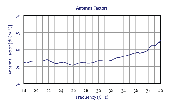
| Antenna Factor | 35.4 to 42.6 dB(m-1) [average: 37.3] |
| Isotropic Gain | 19.1 to 23.6 dBi [average: 21.9] |
| VSWR | 1.12 to 1.77 : 1 [average: 1.42] |
| Return Loss | 11.1 to 25.0 dB [average: 15.9] |
| Maximum Field Strength | >1,000 V/m at 1 m (with 200 W direct waveguide) |
| Radiated Field Strength | See typical field strength graph (10 W and 200 W input) |
| -3 dB Beamwidth | See typical beamwidth graph (E-plane and H-plane) |
| Applicable Standards | FCC, CISPR, EN, ETSI, FAA, MIL-STD-461, RTCA DO-160, SAE |
| Calibration | Individually calibrated per ANSI C63.5, NIST traceable |
| Mounting | 1/4″-20 threaded hole (center of base plate) |
| Horn / Waveguide Dimensions | 2.1″ × 2.8″ × 5.9″ [5.3 × 7.1 × 15 cm] |
| Complete Assembly Dimensions | 5.9″ × 8.7″ × 7.9″ [15 × 22 × 20 cm] |
| Weight | 1 lb [0.5 kg] |
All values are typical, unless specified. All specifications are subject to change without notice.
🔍 Not Sure Which Antenna You Need?
Compare all Com-Power antenna models side-by-side with our interactive selection tool. Filter by frequency range, antenna category, application, polarization, and power handling to find your perfect match.
Compare All Antenna Models →AH-840 Combined-Band Double Ridge Horn Antenna — Frequently Asked Questions
1. What is the Com-Power AH-840 and what is it primarily used for?
The AH-840 is a broadband linearly polarized double ridge waveguide horn antenna covering 18 GHz to 40 GHz in a single unit — combining the full K-band (18–26.5 GHz) and Ka-band (26.5–40 GHz) ranges that would otherwise require two separate antennas. It is used for EMC emissions and immunity testing, effective radiated power (ERP) and effective isotropic radiated power (EIRP) measurements, and substitution-method regulatory compliance work. It is capable of generating field strengths above 1,000 V/m at 1 m with 200 W waveguide drive, and is the single-antenna solution for complete 5G FR2 mmWave band coverage.
2. What are the AH-840’s key electrical and mechanical specifications?
Frequency: 18 GHz – 40 GHz. Gain: 19.1–23.6 dBi (average 21.9 dBi), typical 15–25 dBi across the full band. Power handling: 10 W with the waveguide-to-coax adapter, or up to 200 W direct to the waveguide flange. Field capability: >1,000 V/m @ 1 m with 200 W direct drive. VSWR: 1.12–1.77 (average 1.42:1); 2.0:1 worst-case. Antenna factor (1 m): 35.4–42.6 dB(m−1) (average 37.3). Polarization: linear. Connector: 2.92 mm (K-type) female. Impedance: 50 Ω. Waveguide: precisely tuned for 18–40 GHz; removable adapter. Construction: high-grade corrosion-resistant aluminum, painted for added protection. Horn/waveguide size: 2.1″ × 2.8″ × 5.9″. Complete assembly: 5.9″ × 8.7″ × 7.9″. Weight: 1 lb (0.5 kg). Calibration: individual per ANSI C63.5 with NIST traceability; ISO 17025 available. 3-year warranty.
3. Why does the AH-840’s combined 18–40 GHz range matter?
The complete 5G NR FR2 mmWave spectrum spans from 24 GHz to 52 GHz, with active deployment in the 24 GHz (n258), 28 GHz (n257, n261), 37 GHz (n260), and 39 GHz bands — all falling within 18–40 GHz. Automotive radar uses 24 GHz short-range, and its harmonics fall into Ka-band. Satellite communication covers K-band downlinks (17.7–21.2 GHz) and Ka-band uplinks (27.5–31 GHz). MIL-STD-461G RE103 requires coverage to 40 GHz. A single AH-840 handles all of these applications without the cost, storage, and setup-time overhead of two separate antennas (the AH-826 + AH-640 pair).
4. Which EMC standards and applications use the AH-840’s frequency range?
• FCC (Federal Communications Commission regulations for 5G, intentional radiators, and mmWave)
• FCC Part 15 Subpart C/E (24 GHz SRR, U-NII devices, unlicensed mmWave)
• FCC Part 30 (Upper Microwave Flexible Use Service — 24, 28, 37, 39, 47 GHz)
• CE / EN standards (European radiated emissions and immunity)
• CISPR 32 / EN 55032 (ITE and multimedia emissions)
• CISPR 16-1-4 (site validation above 1 GHz)
• MIL-STD-461G RE103 and RS103 (military EMI/EMS to 40 GHz — AH-840 covers the full mmWave portion)
• RTCA DO-160 Section 20/21 (airborne equipment immunity/emissions)
• FDA / medical IEC 60601-1-2 for mmWave medical radar and imaging
• SAE standards for automotive radar and 5G-V2X testing
• ETSI EN 303 645 / EN 301 489 (wireless product conformity)
• 3GPP TS 38.101-2 (5G NR FR2 RF performance across n257, n258, n260, n261)
5. What real-world products and systems rely on AH-840 testing?
• Complete 5G NR FR2 mmWave equipment: base stations, small cells, CPE, handsets across all FR2 bands (24, 28, 37, 39 GHz) — one antenna, one test sequence
• Automotive radar: 24 GHz short-range radar fundamental plus 77 GHz long-range radar harmonics (second harmonic falls into Ka-band)
• Satellite terminals: K-band downlink (17.7–21.2 GHz), Ka-band uplink (27.5–31 GHz), LEO/GEO user equipment
• Point-to-point microwave links: 18/23 GHz licensed backhaul, E-band precursors
• Aerospace/defense: K/Ka-band SATCOM, military radars, electronic warfare, seeker heads
• Medical mmWave: body-scan imaging, radar-based vital-sign monitors, emerging terahertz-precursor systems
• Industrial: 24 GHz motion sensors, tank-level radar, industrial automation mmWave links
• Research: 5G/6G antenna arrays, mmWave RFIC characterization, phased-array OTA testing, broadband radar R&D
6. What are the key advantages of combining K-band and Ka-band in a single antenna?
Three practical benefits make the AH-840’s combined-band design valuable: (1) No antenna change mid-test sequence — regulatory sweeps from 18 GHz to 40 GHz complete without the 10–20 minutes of swap and re-align time required for separate antennas; (2) Lower capital cost than purchasing AH-826 and AH-640 separately while getting essentially the same frequency coverage; (3) Compact footprint — one antenna to store, calibrate, transport, and manage on your asset roster. The tradeoff is slightly lower peak gain (15–25 dBi vs. ≥23 dBi for the dedicated single-band horns) and marginally less focused band-edge performance. For labs running mixed mmWave programs, the consolidation benefit typically outweighs the specification delta.
7. Why does the AH-840 come with a removable waveguide-to-coax adapter, and when should I bypass it?
The AH-840 uses a precisely tuned waveguide as its native feed. The included removable waveguide-to-coax adapter (2.92 mm K-type connector) lets you drive the antenna with standard coaxial amplifiers, receivers, and signal generators for emissions and low-power immunity work. Use the adapter for emissions receive measurements and for immunity transmit up to 10 W — this is the simpler, more flexible configuration. Remove the adapter and drive the waveguide flange directly when: (a) you need the full 200 W CW rating for maximum field strength (>1,000 V/m at 1 m); (b) your power amplifier has a waveguide output; or (c) you need to minimize coaxial loss at the upper end of the band. Direct waveguide feed eliminates the ~0.5–1 dB of adapter loss and avoids connector damage at high continuous power.
8. How does the AH-840 compare with the AH-826 + AH-640 combination?
The AH-826 + AH-640 pair covers the same 18–40 GHz range as the AH-840 with two separate antennas. Tradeoffs:
• AH-840 advantages: single antenna, no swap between K and Ka-band tests, lower combined cost, one calibration certificate to manage, lighter total weight (1 lb vs. 3 + 1.5 = 4.5 lbs)
• AH-826 + AH-640 pair advantages: higher individual peak gain (≥23 dBi each vs. 15–25 dBi for the AH-840), dedicated optimized design per band, simultaneous use (one on receive while the other transmits, or parallel measurements), continued operation if one antenna is being recalibrated
Choose AH-840 for lab consolidation, single-operator mmWave test stations, portable rigs. Choose the AH-826 + AH-640 pair for maximum per-band performance or dual-polarization / parallel-measurement setups.
9. Should I choose the AH-840 or the AH-8055 for my 5G / mmWave work?
These two antennas cover fundamentally different bands and serve different use cases:
• AH-8055 (800 MHz–5 GHz, 450 W, up to 1,670 V/m): high-field sub-6 GHz testing — 5G FR1 bands, Wi-Fi, LTE, Bluetooth, automotive immunity at 200 V/m, MIL-STD-461 RS103 sub-6
• AH-840 (18–40 GHz, 200 W direct waveguide, >1,000 V/m): mmWave testing — 5G FR2 bands, Ka-band satellite, automotive 24 GHz radar, MIL-STD-461 RS103 mmWave portion
A complete modern EMC lab typically owns both, covering sub-6 GHz and mmWave with two well-chosen antennas. If your product mix includes FR1-only wireless (most current smartphones, IoT, automotive infotainment), start with AH-8055. If your product is FR2 or K/Ka-band, start with AH-840. If both, own both.
10. How much amplifier power do I need to hit common field strengths with the AH-840?
Using E ≈ √(30·P·G) / d at 1 m and 22 dBi average gain:
• 10 V/m: ~0.02 W
• 30 V/m: ~0.2 W
• 100 V/m: ~2.1 W — 10 W amp with coax adapter
• 200 V/m: ~8.5 W — 25–50 W amp (near adapter limit, consider waveguide)
• 500 V/m: ~53 W — requires direct waveguide drive
• 1,000 V/m: ~210 W — direct waveguide, near the 200 W ceiling
Stay within the 10 W adapter / 200 W waveguide limits. Add 3–6 dB headroom for VSWR, cable loss, and modulation crest factor. At the upper band (36–40 GHz), gain is near the low end (~15 dBi), so more power is needed than the average suggests — plan accordingly. For 40 GHz field uniformity per IEC 61000-4-3, use a calibrated mmWave isotropic E-field probe at the EUT location.
11. What is the 2.92 mm K-type connector and why does the AH-840 use it?
The 2.92 mm connector (also called K-type, named for the K-band it was originally designed for) is a precision RF coaxial interface rated to 40 GHz — precisely matching the AH-840’s upper frequency. It is mechanically compatible with SMA, so a 2.92 mm plug mates with an SMA jack, but only 2.92 mm-to-2.92 mm mating achieves full performance above 18 GHz. For the AH-840 always use 2.92 mm on all coaxial joints: at the antenna, at the cable, and at the instrument. SMA connectors in the signal path will add significant insertion loss and VSWR degradation above 24 GHz, corrupting the measurement.
12. What setup and cable considerations are critical at 18–40 GHz?
• Cable loss is severe at 40 GHz — typical low-loss microwave cables lose 0.5–1.5 dB per foot at the top end. Keep coax runs under 1 m; use phase-stable precision microwave cable rated to 40 GHz
• Use the waveguide-to-coax adapter location wisely — place it at the antenna (short coax to instrument) rather than at the amplifier (long coax to antenna)
• Connector torque — 2.92 mm connectors torque to 8 in-lb with a calibrated wrench; never finger-tighten
• Inspect connectors under magnification before every mate; mmWave pins are unforgiving of dust, oxidation, or pin damage
• Waveguide flange care — the AH-840’s waveguide uses precision flanges; protect them with dust caps when not mated
• Test distance — at mmWave, far-field starts at < 30 cm for most EUTs; 1 m is standard for EMC, 3 m for some full-chamber tests
• Absorber validation — chamber absorbers must be rated for 40 GHz; verify NSA or field uniformity across the full band before first use
13. Why is calibration especially important across 18–40 GHz, and what does NIST-traceable mean?
The 18–40 GHz range spans more than an octave, and antenna factor, gain, and VSWR all vary significantly across it. At the upper Ka-band end, small mechanical variations (flange flatness, connector wear, waveguide tuning) can produce 3–5 dB measurement errors without proper calibration. Com-Power calibrates every AH-840 individually per ANSI C63.5 with NIST traceability — a documented, unbroken chain of measurement comparisons back to U.S. National Institute of Standards and Technology primary standards. The calibration certificate includes gain and antenna factor vs. frequency, which your receiver applies automatically for accurate field-strength or emissions readings. ISO 17025 accredited calibration is available on request when your lab’s accreditation body requires an externally audited certificate. Recalibrate annually or after mechanical stress.
14. What applications beyond EMC testing does the AH-840 support?
• 5G / 6G research and development — OTA verification of phased arrays, beam-forming characterization, RFIC testing across full FR2
• Antenna pattern measurement — rotate an antenna-under-test in an anechoic range; AH-840 receives across the full 18–40 GHz sweep in one setup
• EIRP / ERP substitution measurement — calibrated reference antenna for measuring absolute radiated power of mmWave transmitters
• Chamber characterization — site validation, reflection coefficient measurement, SVSWR, field uniformity across complete mmWave range
• Radar testing — 24 GHz fundamentals plus 77 GHz radar harmonics (second harmonic at 39 GHz falls within AH-840 range)
• Surveillance / signal intelligence — broadband directional K/Ka-band reception for detection and classification
• Education and research — single-antenna solution for university labs covering both K- and Ka-band experiments
• Production test — single-station test of products whose operational frequencies span K- and Ka-band
15. What are the AH-840’s key design advantages?
• Complete 18–40 GHz coverage in one antenna — spans K- and Ka-band without swapping
• Precisely tuned waveguide for broadband flatness across the full range
• Flexible drive — 10 W with coax adapter, 200 W direct waveguide — emissions and high-field immunity
• Field capability >1,000 V/m at 1 m with 200 W waveguide drive
• Low VSWR (average 1.42:1) — efficient power transfer, minimal reflected energy
• Removable waveguide-to-coax adapter — choose coax convenience or waveguide power as needed
• Precision 2.92 mm (K-type) connector — correct mmWave interface rated to 40 GHz
• Extremely lightweight (1 lb) — easy to handle, mount, and transport
• High-grade corrosion-resistant aluminum, painted — indoor/outdoor daily use
• Individual NIST-traceable calibration; ISO 17025 available
• Both transmit and receive capable — emissions and immunity in one antenna
• 3-year standard warranty — extended protection on the investment
• Consolidates AH-826 + AH-640 capability — lab consolidation, capital savings
16. When should engineers select the AH-840 over other Com-Power antennas?
Select the AH-840 when any of the following applies:
• You need complete 5G NR FR2 mmWave coverage across all bands (24, 28, 37, 39 GHz) with a single antenna — ideal for cellular OEMs, infrastructure vendors, and 5G labs
• Your lab performs mixed K-band and Ka-band testing and you want to eliminate antenna swaps
• You need to consolidate two antennas (AH-826 + AH-640) into one for capital savings, portability, or storage
• Your tests include automotive 24 GHz radar fundamentals AND 77 GHz harmonic coverage (39 GHz second harmonic)
• You work with full K/Ka-band satellite systems (downlinks and uplinks in different sub-bands)
• Your compliance standard is MIL-STD-461G RE103 to 40 GHz, DO-160, FCC Part 30, or CISPR 32 with broadband mmWave requirements
• You need EIRP/ERP substitution measurements across an 18–40 GHz sweep
• You run a portable or consolidated test rig where storage and transport weight matter
Choose the AH-826 if you only need 18–26.5 GHz (24 GHz automotive, 5G n257/n258, K-band satellite). Choose the AH-640 if you only need 26.5–40 GHz (28/39 GHz 5G, Ka-band satellite, 77 GHz harmonics). Choose the AH-118 for 1–18 GHz, or the AH-8055 for high-field 800 MHz–5 GHz immunity. For complete sub-6 + mmWave coverage, pair AH-8055 with AH-840.
Application Notes (PDF)
- AN-107 — What is Antenna Factor?
- AN-106 — Use of Antenna Factor for EMC Measurements
- Selecting the Right EMI Antenna
- Considerations when Selecting an Antenna for RF Immunity Testing
- EMC Antenna Calibration Requirements, Methodologies, and Best Practices
- NIST Antenna Calibration Services — Com-Power Capabilities and Traceability
- Com-Power EMC Antenna Product Line — Complete Specifications
- Accounting for Ambient Noise
Interactive Tools
- Antenna Finder Wizard
- Com-Power Antenna & Field Strength Calculator
- Com-Power EMC Compliance Limits Calculator
- Com-Power Cable Loss & Attenuation Calculator
- Com-Power VSWR / Return Loss / Mismatch Loss Calculator
- Com-Power Free Space Path Loss & Link Budget Calculator
Industry Applications
- EMC Considerations for IoT and Smart Home Devices
- Automotive EMC Testing — ISO 11452 / CISPR 25
- 5G Equipment EMC Testing — New Challenges in EMC Compliance
- Medical Device EMC Compliance — IEC 60601-1-2 Essentials
- EV Charging Systems — EMC Requirements and Compliance
Blog Articles


Quote Request
Other EMC Test Equipment
- Absorbing Clamps
- Antenna Kits
- Antenna Masts - Automated and Manual
- Antennas
- Bulk Current Injection probes
- CDNs - Coupling Decoupling Network
- Comb Generators
- Conducted Immunity Test Systems
- Current Monitor Probes
- Current Probe Calibration Fixtures
- EM Clamps
- Feed Through Capacitor
- ISNs - Impedance Stabilization Network
- LISNs - Single Phase
- LISNs - TEMPEST
- LISNs - Three Phase
- Magnetic Field Generator
- Near Field Probes
- Power Amplifiers
- Pre-compliance Emissions Test Systems
- Preamplifiers
- Spectrum Analyzers
- Surge Generators
- System Controllers
- Transient Limiters
- Tripods For EMC
- Turntables