
Preamplifier for Microwave Testing
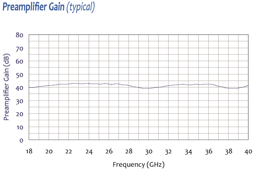
- The PAM-840A is a battery-powered millimeter-wave preamplifier covering 18 GHz to 40 GHz with 37–40 dB gain — the daily-use mmWave preamp for radiated EMC testing in the FR2 band.
- Noise figure < 5 dB max @ 25°C with ±2.5 dB gain flatness and +10 dBm minimum output at 1 dB compression; +40 dB reverse isolation protects the EMI receiver front end.
- Covers 5G FR2 mmWave (24, 28, 37, 39 GHz), automotive radar at 24 and 38 GHz, satellite communications, point-to-point microwave links, and FCC Part 15 / CISPR 32 harmonic testing through 40 GHz.
- Mount at the microwave horn antenna (such as the AH-840) to offset mmWave coax and waveguide losses that exceed 1 dB per inch with inexpensive cable; place as close to the antenna as physically possible.
- Characterizes 5G FR2 spurious emissions and harmonics from devices, modules, and small cells; exposes weak high-order content from oscillators, mixers, and frequency multipliers.
- Maintains SNR over longer, higher-loss cable runs in compact antenna ranges and large mmWave chambers; supports antenna pattern checks and quiet-zone verification by lifting low sidelobes above noise.
- Compact bench-top chassis — 7.6″ × 5.95″ × 2.17″ (192 × 151 × 55 mm), 2.5 lbs (1.13 kg) with precision 50Ω 2.92 mm female (K-type) connectors and 6 V / 2 Ah NiMH battery.
- Individually NIST-traceable calibrated; ISO 17025 calibration available on request. Three-year warranty.
Features
- ▸ Millimeter-wave EMI/EMC preamplifier covering 18 GHz to 40 GHz — bridges the gap above 18 GHz where most receiver and antenna combinations have severely degraded sensitivity; the standard mmWave preamp for the Com-Power lineup.
- ▸ High 37 dB typical gain with ±2.5 dB flatness — substantial gain to compensate the heavy losses typical of mmWave coaxial cables and waveguide components; consistent flatness across the band simplifies amplitude correction.
- ▸ Low noise figure of <5 dB at 25°C — excellent for the 18–40 GHz band, where noise figure performance is fundamentally harder to achieve than at lower frequencies.
- ▸ +10 dBm output @ 1 dB compression — supports linear amplification of moderate-amplitude DUT fundamentals at mmWave frequencies without saturation distortion.
- ▸ ~40 dB reverse isolation — protects sensitive horn antennas and mmWave probes from local oscillator leakage out of the connected EMI receiver.
- ▸ Precision 50Ω 2.92 mm (K-type) input/output connectors — rated for the full 40 GHz range; designed for use with torque wrench discipline to maintain mmWave measurement repeatability.
- ▸ 5G FR2 mmWave (24, 28, 37, 39 GHz) emissions verification — covers all 5G FR2 bands plus automotive radar at 24 GHz, RTCA DO-160 extended range, MIL-STD-461 RE102 upper band, and CISPR 32 emissions through 40 GHz.
- ▸ Pairs with mmWave horn antennas (AH-840, AH-826, AH-640) — mount at the horn feed to overcome mmWave coax/waveguide loss before signals reach the cable; placement is critical at these frequencies.
- ▸ Characterizes 5G FR2 spurious and harmonics — ideal for measuring leakage in 24–40 GHz devices, modules, and small cells; exposes weak high-order content from oscillators, mixers, and frequency multipliers.
- ▸ Speeds mmWave pre-scans — allows wider RBW while preserving visibility of narrow, low-level harmonic and spurious lines.
- ▸ Battery operation reduces supply-noise coupling — internal 6 V / 2 Ah NiMH battery pack supports placement on antenna booms or masts without AC power coupling; AC adapter operation also available.
- ▸ Receive-path use only — designed exclusively for amplifying received signals; not intended for transmit or immunity injection chains at mmWave.
- ▸ Compact bench-top form factor — 7.6″ × 5.95″ × 2.17″ (192 × 151 × 55 mm), 2.5 lbs (1.13 kg); easy to mount near horns on antenna positioners or chamber masts.
- ▸ Individually calibrated, NIST-traceable — calibration data and certificate ship with each unit; ISO 17025 accredited calibration available on request.
- ▸ Three-year standard warranty — backed by manufacturer support.
Specifications
| Model | PAM-840A |
|---|---|
| Application | Millimeter-Wave Microwave Preamplifier (EMI/EMC, 5G FR2) |
| Frequency Range | 18 GHz to 40 GHz |
| Gain | 37 dB (typical) |
| Gain Flatness | ± 2.5 dB |
| Noise Figure | < 5 dB @ 25°C |
| Output Power @ 1 dB Compression | +10 dBm (min) |
| VSWR (Input/Output) | 2.25:1 (max) |
| Reverse Isolation | 40 dB (typical) |
| RF Input/Output Impedance | 50 Ω |
| Connector Type | 2.92 mm (K-type, female) |
| Battery Pack | 6 V, 2 Ah NiMH (rechargeable) |
| DC Power Supply | +15 VDC, 500 mA |
| Dimensions (L × W × H) | 7.6″ × 5.95″ × 2.17″ (192 × 151 × 55 mm) |
| Weight | 2.5 lbs (1.13 kg) |
| Calibration | Individually calibrated, NIST traceable; ISO 17025 accredited available on request |
| Warranty | Three-year standard warranty |
All values are typical, unless specified. All specifications are subject to change without notice.
🔍 Not Sure Which Preamplifier You Need?
Find the perfect Com-Power preamplifier for your EMC testing needs with our interactive finder wizard. Filter by frequency range, gain, noise figure, and application to match your exact requirements.
Find Your Preamplifier →PAM-840A Millimeter-Wave Microwave Preamplifier – Frequently Asked Questions
1. What is the PAM-840A preamplifier and what is it designed for?
The PAM-840A is a wideband millimeter-wave benchtop preamplifier covering 18 GHz to 40 GHz with a typical gain of 40 dB. It is designed to amplify very weak emissions in the mmWave band so they can be measured reliably with EMI receivers or spectrum analyzers. Its primary role is to compensate for the significant cable, connector, and path losses that dominate above 18 GHz and to lift DUT emissions above the receiver noise floor at frequencies where every measurement step counts double.
2. Why is 18 GHz to 40 GHz coverage important in modern EMC testing?
Modern compliance testing increasingly extends into the millimeter-wave band because of products using 5G FR2 (24–40 GHz), automotive radar at 24 GHz and 77 GHz, high-data-rate point-to-point microwave links, satellite communication modules, mmWave sensors, and industrial radar systems. FCC Part 15 harmonic testing can also push a product's measurement range into this band when fundamentals are above 6 GHz. Most receiver and analyzer front ends lose significant sensitivity above 18 GHz, making an external preamp essentially mandatory for credible measurements at these frequencies.
3. How does the PAM-840A differ from the PAM-840H and PAM-118A?
The PAM-840A and PAM-840H share the same 18–40 GHz range but differ in gain: the PAM-840A delivers 40 dB typical, while the PAM-840H delivers 50 dB typical. The PAM-840A is the general-purpose choice with better dynamic range; the PAM-840H is the specialty tool for extreme-sensitivity situations. The PAM-118A covers 500 MHz to 18 GHz; together with the PAM-840A, it forms a complete 500 MHz to 40 GHz preamp chain for labs that need full mmWave coverage.
4. How does the PAM-840A compare with waveguide-based mmWave amplifiers?
Some mmWave amplifiers use waveguide input/output (WR-28, WR-22, WR-19) for lowest loss at frequencies above 26 GHz. The PAM-840A uses coaxial K-type or 2.92 mm connectors across its full 18–40 GHz range, trading some very-high-frequency insertion loss for much greater practical flexibility. Waveguide amplifiers are optimized for a single band; the PAM-840A covers the entire 18–40 GHz span in a single unit with consistent gain and calibration. For EMC radiated emissions work, coaxial preamps are the practical choice because receive antennas and cable chains in EMC chambers are coaxial-based.
5. What are the real-world workflow advantages of the PAM-840A?
At 40 GHz, high-quality coaxial cable loss can exceed 1 dB per foot. A 10-meter cable run to the receiver can eat 30+ dB of signal, which without amplification would put most DUT emissions into the noise. The PAM-840A's 40 dB gain compensates for these losses and recovers measurement sensitivity. It also enables shorter dwell times and wider RBW in the expanding mmWave portion of modern compliance scans, reducing total test time. And its single-unit coverage from 18 to 40 GHz eliminates the need to swap preamps mid-scan.
6. What standards and frameworks does the PAM-840A support?
The PAM-840A supports FCC Part 15 harmonic testing, CISPR 32 for multimedia above 18 GHz, CISPR 11 above 18 GHz, MIL-STD-461 RE102 extended range, RTCA DO-160 RF emissions, and automotive standards including CISPR 25 where radar-band testing is required. It also supports FCC 47 CFR Part 15 Subpart E for UWB harmonic measurements, 5G NR FR2 measurements under various wireless certification regimes, and general microwave spectrum monitoring. Each unit ships with NIST-traceable calibration; ISO/IEC 17025 accredited calibration is available.
7. How is the PAM-840A used for radiated emissions testing?
The PAM-840A is placed between a mmWave receive antenna (typically a standard-gain horn such as the Com-Power AH-840 series) and the EMI receiver or spectrum analyzer. Placement directly at the antenna is particularly important at mmWave because every additional inch of cable between antenna and preamp translates into measurable signal loss. The antenna-preamp pair is then connected to the receiver with a single coaxial run, calibrated end-to-end or corrected using the preamp's individual gain data.
8. Can the PAM-840A be used for 5G FR2 testing?
Yes. The PAM-840A's 18–40 GHz range covers all the major 5G FR2 bands including n257 (26.5–29.5 GHz), n258 (24.25–27.5 GHz), n260 (37–40 GHz), and n261 (27.5–28.35 GHz). For 5G FR2 spurious emissions, harmonic characterization, and beam-pattern radiated measurements, the PAM-840A provides the receive-path amplification needed to see very low-level content alongside strong fundamentals. It is equally useful for 802.11ad/ay (WiGig) compliance work in the 60 GHz band's harmonic downconversion chains where intermediate frequencies fall in the 18–40 GHz range.
9. Why is low noise figure particularly important at mmWave frequencies?
At mmWave frequencies, the signal arriving at the antenna is already very weak because of free-space path loss (which scales with frequency squared) and limited DUT radiation patterns. Any noise added by the preamp significantly degrades the measurement. The PAM-840A's low noise figure (typically <4 dB) is the result of careful GaAs or GaN device selection and matching networks optimized for the 18–40 GHz band. By the Friis cascade rule, the preamp's noise figure dominates the entire system noise figure when placed ahead of lossy cables and the receiver — so low noise figure here translates directly into better sensitivity.
10. What does a 40 dB gain figure mean for mmWave measurements?
The PAM-840A's 40 dB gain typical is specified across the full 18–40 GHz range, not just at a single frequency. mmWave preamps tend to have more gain variation across their range than lower-frequency units because of the physics of transistor and matching-network behavior at these frequencies. The 40 dB specification is an average with some ripple, and the individual calibration data provided with each unit corrects for the actual per-frequency gain. This is why per-unit calibration becomes more important (not less) as frequency increases.
11. What kinds of real-world products are good candidates for PAM-840A testing?
The PAM-840A covers the band where many modern RF-intensive products are evaluated: 5G FR2 smartphones and base stations, mmWave small cells, automotive radar sensors (24 GHz and higher harmonics), satellite ground-station modules, mmWave point-to-point backhaul radios, drone RF systems, ISM-band equipment at 24/60 GHz, industrial level sensors, and high-speed digital interfaces with very short bit periods that produce harmonics in the mmWave band.
12. Can the PAM-840A be used in over-the-air (OTA) test setups?
Yes. Many OTA test setups for mmWave products use anechoic chambers with horn antennas at specified distances, and the path loss plus cable loss can exceed 60 dB. The PAM-840A is essential for recovering measurable signal levels in these setups. It is used for spurious emissions measurements, harmonic and subharmonic characterization, radiation pattern testing, and beam-steering verification on 5G FR2 and automotive mmWave products. It is compatible with standard mmWave test chamber instrumentation and horn antennas.
13. Why do individual calibration and NIST traceability matter at mmWave frequencies?
Above 18 GHz, measurement uncertainty budgets tighten significantly because of contributions from cable stability, connector torque, temperature sensitivity, and amplifier gain ripple. Each PAM-840A is individually calibrated with gain-versus-frequency data traceable to NIST through the SI, and this correction is loaded into the receiver or post-processing chain. Without per-unit calibration, gain ripple of 3–5 dB across the band would directly translate into amplitude errors. ISO/IEC 17025 accredited calibration is available for labs under accredited quality systems, and annual recalibration is standard practice at these frequencies.
14. What mechanical and RF interface details matter for daily use of the PAM-840A?
The PAM-840A uses precision coaxial connectors rated for 40 GHz operation (typically 2.92 mm / K-type, which mate with SMA but offer higher frequency performance). Users must handle these connectors with proper torque wrenches and avoid over-torquing, as damage to mmWave connectors can introduce significant measurement errors. The unit is benchtop in form factor with battery or external DC power. Cable selection matters as much as the preamp itself: low-loss, phase-stable mmWave cables (such as SUCOFLEX or similar) should be used for all connections above 18 GHz to avoid wasting the preamp's gain on cable loss.
15. When is the PAM-840A a better choice than using a downconverter?
Some labs use harmonic mixers or external downconverters to translate mmWave signals down to the receiver's native range. That approach works but introduces conversion loss, LO phase noise, image response issues, and calibration complexity. A direct-measurement chain using a PAM-840A is cleaner, has fewer error sources, and requires no LO management. For labs that can afford a receiver or analyzer with native coverage to 40 GHz (or access to one through an extended-range downconverter with lower complexity), a preamp-plus-native-receiver chain gives cleaner and more defensible measurements.
16. Why would an EMC lab choose the PAM-840A as a long-term investment?
The PAM-840A opens up the 18–40 GHz band for compliance measurement in a way that is otherwise extremely difficult. As 5G FR2, automotive radar, satellite IoT, and mmWave digital products continue to grow in volume, labs that can credibly certify these products need mmWave amplification. The PAM-840A offers the right balance of gain, noise figure, and frequency coverage in a single unit with individual NIST calibration. Combined with a PAM-118A for the sub-18 GHz range, it gives a lab complete 500 MHz to 40 GHz radiated emissions capability — which is increasingly the baseline expectation for modern compliance testing.
Noise Floor, Noise Figure & System Sensitivity
17. What is the difference between noise floor and noise figure, and why does it matter for the PAM-840A?
These two terms are frequently confused but describe completely different things. Noise floor is a measured power level expressed in dBm or dBµV — it tells you the lowest signal amplitude that can be distinguished from background noise in a specific measurement setup at a specific resolution bandwidth. Noise figure is a property of the amplifier itself expressed in dB — it tells you how much the amplifier degrades the signal-to-noise ratio compared to a theoretical perfect amplifier at room temperature. The PAM-840A has a typical noise figure of <4 dB across the 18–40 GHz band, which is a device characteristic. The noise floor you actually see on your receiver depends on the preamp's noise figure, the RBW setting, cable losses ahead of the preamp, ambient temperature, and the receiver's own noise figure. A good mmWave preamp lowers the effective system noise figure dramatically, which in turn lowers the achievable measurement noise floor — but the two are not the same number.
18. How does the PAM-840A's noise figure affect the overall system noise floor?
At mmWave frequencies, the receiver's native noise figure is typically very poor (often 25–35 dB above 18 GHz) because downconverters, mixers, and internal amplifiers struggle at these frequencies. The Friis cascade rule determines how the noise figures of chained components combine. When the PAM-840A with its <4 dB noise figure and 40 dB gain sits ahead of a cable and receiver, its gain dominates the cascade equation, and the system noise figure collapses to approximately the PAM-840A's own noise figure plus the loss of anything ahead of it. The receiver's 25–35 dB noise figure becomes almost entirely irrelevant. The result is a system noise floor that is dramatically lower — often 20 to 30 dB lower — than what the same receiver would produce without the preamp. At mmWave, the external preamp is not just helpful; it is often the difference between being able to make a measurement and not.
19. Why does a preamp with 40 dB gain not lower the noise floor by 40 dB?
This is a common intuition that is slightly wrong. Adding 40 dB of gain raises both the signal and the noise by 40 dB, so on the display the apparent noise floor rises rather than falls. What actually improves is the signal-to-noise ratio at the output relative to the receiver's own noise contribution. Because the receiver's noise now sits well below the amplified noise from the preamp and antenna, the overall sensitivity is limited by the preamp's noise figure rather than the receiver's. The net gain in measurement sensitivity is roughly (receiver noise figure − preamp noise figure − cable loss ahead of preamp). For a typical PAM-840A setup at mmWave, this can work out to 20–30 dB of real sensitivity improvement because the receiver noise figure contribution that gets swamped out is so large.
20. What limits the noise floor improvement I actually see with the PAM-840A in my setup?
Several factors can eat into the theoretical improvement, and at mmWave frequencies these effects are amplified. Cable loss between the antenna and the preamp is especially damaging above 18 GHz — typical coax can lose 1–2 dB per foot at 40 GHz, so even a short cable between antenna and preamp adds directly to the effective system noise figure. Antenna-side placement is not just best practice at mmWave, it is essential. Temperature raises the thermal noise floor by about 0.01 dB per degree Celsius. Strong ambient signals in-band are rare at mmWave but possible near 5G base stations or automotive radars. Connector torque on 2.92 mm or K-type connectors is critical — improper torque can add 1–3 dB of loss and significant gain ripple. And resolution bandwidth directly scales the displayed noise: halving RBW drops the displayed noise floor by 3 dB regardless of preamp performance.
ESD Protection & Preamp Safety
21. Why are mmWave preamplifiers like the PAM-840A vulnerable to static electricity?
mmWave preamplifiers use GaAs pHEMT or GaN HEMT transistors at their front end, which are selected specifically for their low noise figure and high gain per stage at frequencies above 18 GHz. These same device characteristics — extremely thin gate oxide, very small channel dimensions, ultra-high input impedance — make them even more sensitive to ESD than lower-frequency preamps. A static discharge of just a few tens to a few hundred volts, which a person may not even feel, can punch through the gate of a mmWave front-end FET and either completely kill the device or, worse, damage it subtly so that the gain drops by a few dB or the noise figure rises by a few dB without any other visible failure. At mmWave frequencies, where measurement uncertainty is already tight, an ESD-degraded preamp silently producing 2–3 dB errors across the band can go undetected for months.
22. How does static electricity reach a preamp connected to an antenna through a coaxial cable?
This is the most common failure mode in EMC labs. An operator handles the antenna — mounts it on a tripod, adjusts its position, changes polarization — and in doing so accumulates a static charge on their body (from walking across carpet, removing a sweater, or just moving around in a dry room). When they touch the antenna, the static discharges through the antenna element, into the coaxial feedline, and directly into the PAM-840A's RF input. The coaxial cable is a low-impedance path that efficiently delivers the entire ESD pulse to the preamp's sensitive front end. Because the discharge happens in nanoseconds, there is essentially no time for the preamp's internal protection to respond, and damage is instant. At mmWave the input connector is typically a 2.92 mm or K-type with very small center-conductor dimensions, which concentrates the ESD energy even more aggressively onto the front-end device.
23. What practical steps prevent static from damaging the PAM-840A through the antenna?
Adopt a disciplined ESD protocol any time the antenna or RF chain is being handled. Because mmWave preamps are the most sensitive in the product line, this discipline is especially important:
• Ground yourself before touching the antenna — wear an ESD wrist strap connected to the chamber ground, or at minimum touch a grounded metal surface (the chamber wall, a grounded bench, the antenna mast base) immediately before handling the antenna.
• Disconnect the preamp input before making major antenna adjustments. A disconnected preamp input is immune to ESD through the antenna path.
• Use an ESD-rated inline attenuator or limiter at the preamp input if frequent antenna handling is unavoidable. Even a 3 dB attenuator provides some protection, though at mmWave the attenuator itself must be rated for the full 40 GHz range.
• Cap the antenna connector when it is not connected to the preamp — this prevents static buildup on the center pin. Use only high-quality mmWave-rated caps.
• Humidify the chamber to 40–50% relative humidity if possible; ESD events are dramatically less common at normal humidity than in dry environments.
• Turn off the preamp before connecting or disconnecting RF cables. Unpowered preamps survive ESD events better than powered ones.
• Use torque wrenches on every mmWave connection — improper torque can itself cause arc discharges at the connector interface under certain conditions.
24. What about ESD through the DC power input or chassis of the PAM-840A?
Less common than the RF path but still possible. Best practices: plug the PAM-840A's DC adapter into a grounded outlet, not a floating or ungrounded power strip. When operating on battery, the chassis can float relative to the chamber ground — use a chassis ground strap to the chamber reference plane if the preamp is operating inside a chamber. Avoid carrying the preamp across a carpeted area and setting it directly into the RF chain without first touching it to a grounded surface. If the preamp has been stored or shipped, let it sit on a grounded bench for a few seconds before connecting any cables to it. mmWave preamps are often shipped in ESD-safe packaging; use the same packaging for storage between uses.
25. How do I protect the PAM-840A during antenna polarization changes and tripod adjustments?
This is a high-risk moment because the operator is actively handling the antenna. Recommended workflow: (1) before approaching the antenna, touch a grounded metal surface to discharge yourself; (2) if the test is paused, power down the preamp or disconnect its input cable; (3) make the antenna adjustment; (4) touch the grounded surface again before reconnecting or powering up the preamp. This adds maybe 15 seconds to each adjustment but dramatically reduces ESD risk. For automated antenna masts with mmWave horns at the boom, the same principle applies at maintenance time — ground yourself before handling cables or connectors on the mast, and be especially careful with the short, often-rigid mmWave cable runs near the antenna.
26. How do I tell if the PAM-840A has been damaged by ESD?
Subtle ESD damage does not always produce a dead preamp; often it produces a degraded one. At mmWave, degradation is especially hard to spot casually. Warning signs include: gain that reads lower than the calibration data by 1–3 dB across the full band or in a specific frequency range; noise figure that has clearly increased (the noise floor with the preamp in circuit is higher than it used to be for the same RBW); frequency response ripple that was not present before; gain that drifts with temperature more than it used to; or increased current draw from the battery or DC supply. At mmWave, even small ripple changes can invalidate 5G FR2 or automotive radar certification measurements. If any symptoms appear, the preamp should be sent to Com-Power for recalibration and evaluation. If damage is confirmed, repair is often possible — input stages can sometimes be replaced without losing the rest of the unit's calibration history.
27. What should I do immediately if I suspect ESD has occurred on the PAM-840A input?
Power down the preamp and disconnect it from the measurement chain. Run a quick sanity check against a known-good reference signal (a mmWave signal generator or comb generator capable of 18–40 GHz) to see if gain is still within specification across the band. Compare the measured gain curve to the original calibration data. If gain is uniformly correct, the preamp may have survived. If gain is off, noise figure appears higher, or the response shape has changed, send the unit to Com-Power for evaluation rather than continuing to use it — a compromised mmWave preamp produces measurements that look plausible but are systematically wrong, which is particularly damaging for 5G FR2, automotive radar, and aerospace measurements where small amplitude errors can invalidate an entire certification. Com-Power offers both 17025 accredited and NIST-traceable recalibration, and repair service for damaged units.


Quote Request
Other EMC Test Equipment
- Absorbing Clamps
- Antenna Kits
- Antenna Masts - Automated and Manual
- Antennas
- Bulk Current Injection probes
- CDNs - Coupling Decoupling Network
- Comb Generators
- Conducted Immunity Test Systems
- Current Monitor Probes
- Current Probe Calibration Fixtures
- EM Clamps
- Feed Through Capacitor
- ISNs - Impedance Stabilization Network
- LISNs - Single Phase
- LISNs - TEMPEST
- LISNs - Three Phase
- Magnetic Field Generator
- Near Field Probes
- Power Amplifiers
- Pre-compliance Emissions Test Systems
- Preamplifiers
- Spectrum Analyzers
- Surge Generators
- System Controllers
- Transient Limiters
- Tripods For EMC
- Turntables