
100 Amps Three-Phase Line Impedance Stabilization Network
- Provides CISPR-compliant 50/250 µH +5Ω network for stable three-phase EMI measurements.
- Supports 9 kHz–30 MHz testing with consistent impedance and strong isolation accuracy.
- Handles up to 100A continuous per line, ideal for high-power industrial 3-phase EUTs.
- Offers remote or local line switching for controlled, repeatable EMI measurements.
- Uses air-core inductors to eliminate saturation and maintain stable impedance under load.
- Complies fully with CISPR 16-1-2 and ANSI C63.4 for commercial EMC qualification.
- Ideal for labs testing large drives, EV chargers, converters, and industrial equipment.
- Supports extended-duration EMC workflows with robust forced-air cooling capability.
- Includes NIST-traceable calibration for impedance, phase, isolation, and insertion loss.
- ISO 17025 accredited calibration available on request for formal compliance programs.
-
Frequency range: 9 kHz to 30 MHz
-
100 A maximum continuous current per line
-
Fully compliant with CISPR 16-1-2 & ANSI C63.4
-
50 Ω, 50/250 µH +5 Ω network for 3-phase Delta & Wye systems
-
Remote or local switching via RLI-100 Remote LISN Interface
-
Integrated transient limiter with dual 5 dB pads
-
Air-core inductors for saturation-free performance
-
Forced-air cooling with two internal cooling fans
-
50 Ω N-type RF measurement port
-
Includes connectors and 10 m fiber-optic cable
-
Three-year standard warranty
General
-
Product Type: Three-Phase LISN
-
Application: Conducted emissions testing
-
Standards: CISPR 16-1-2, ANSI C63.4
-
Network Type: 50 Ω / 50–250 µH +5 Ω
-
Frequency Range: 9 kHz–30 MHz
Insertion Loss
-
9 kHz–150 kHz: <17 to <11 dB
-
150 kHz–30 MHz: <11 dB
Isolation
-
9 kHz–50 kHz: >0 to >40 dB
-
50 kHz–30 MHz: >40 dB
Input Power Ratings (EUT)
-
Maximum Current: 100 A continuous per line
-
AC Voltage: 865 V rms (line–line), 500 V rms (L–G)
-
DC Voltage: 600 V DC
Connections
-
100A receptacle pins (Red, Yellow, Blue, Black, Green)
-
100A plug sockets (input cable)
-
100A receptacle sockets (output side)
-
100A plug pins (EUT cable)
-
RF Port: 50 Ω N-Type (female)
-
Fiber Optic Ports: Avago duplex POF
-
Remote Power Input: 6 VDC, 500 mA
-
Fan Power Input: 15 VDC, 500 mA
Environmental / Cooling
-
Operating Temperature: 5–40 °C (40–104 °F)
-
Cooling: Forced-air, dual internal fans
Product Weight
-
Weight: 184.64 lbs (83.75 kg)

🔍 Not Sure This Is The Right LISN?
Compare all 25 Com-Power LISN models side-by-side with our interactive selection tool. Filter by current, voltage, frequency, and standards to find your perfect match.
Compare All LISN Models →LI-3P-2100 V2.0 Three-Phase V-AMN LISN FAQs
What is the LI-3P-2100 and which equipment power class is it designed to address?
The LI-3P-2100 is a four-conductor, 50Ω, 50/250 μH +5Ω three-phase Line Impedance Stabilization Network (LISN), also known as an Artificial Mains V-Network (V-AMN), rated at 100 amperes per phase. It is the highest-current model in the Com-Power LI-3P-2x series, designed for conducted emissions compliance testing of the largest class of three-phase industrial equipment — including 70 kVA class VFDs, high-power DC fast chargers, large renewable energy inverters, industrial welding systems, heavy-duty UPS installations, and energy storage system converters.
Why does testing large industrial equipment from 9 kHz instead of 150 kHz matter for compliance?
High-power equipment switching at low frequencies — such as large VFDs switching at 2 kHz to 8 kHz, high-power rectifiers, and battery energy storage inverters — produces harmonic currents most intense in the 9 kHz to 150 kHz band. Product standards referencing the CISPR 16-1-2 V-network method require measurements from 9 kHz, and regulatory agencies are increasingly enforcing limits in this sub-band for industrial, clean energy, and EV equipment. A LISN starting only at 150 kHz could allow a product to pass conducted emissions testing while still violating the applicable regulatory limits in the lower sub-band.
Which international EMC standards does the LI-3P-2100 comply with?
The LI-3P-2100 is fully compliant with CISPR 16-1-2 for CE marking and ANSI C63.4 for FCC testing. It supports AS/NZS, VCCI, ISED Canada, and other international standards referencing CISPR 16-1-2 V-network methodology. V-AMN network compliance ensures acceptance by accredited test laboratories and notified bodies for formal certification testing.
What are the maximum EUT power ratings for equipment connected to the LI-3P-2100?
The LI-3P-2100 supports 100 A per phase continuous, 865 V RMS line-to-line, 500 V RMS line-to-ground, and 600 V DC maximum. On a 400 V three-phase supply, 100 A corresponds to approximately 70 kVA, covering the largest three-phase equipment categories subject to conducted emissions testing.
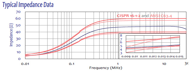
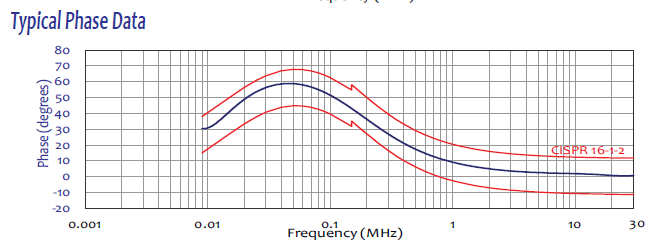
How does the V-AMN 50/250 μH +5Ω network in the LI-3P-2100 maintain impedance accuracy at 100 A?
The LI-3P-2100 uses air-core inductors for all 50/250 μH network elements. At 100 A, ferrite or steel-core inductors would saturate, causing unpredictable inductance reduction and pulling the V-network impedance outside CISPR 16-1-2 tolerances. Air-core construction has no saturation threshold and maintains constant permeability regardless of current, temperature, or frequency, guaranteeing every disturbance voltage measurement is taken against the correct defined impedance reference from 9 kHz through 30 MHz.
Why is the LI-3P-2100 cooling system so critical and how does it work?
At 100 A per phase, ohmic losses in the inductors and conductors far exceed what passive cooling can manage. The LI-3P-2100 uses three user-controlled internal fans drawing air through three 4.5-inch circular rear-panel intakes, exhausting through eight 4-inch square mesh-protected top-cover outlets. The fan system is powered by a dedicated 15 V DC supply on the rear panel. This active thermal management sustains full 100 A continuous operation without derating during extended compliance sequences.
How does the fiber optic remote line switching system improve safety and efficiency at 100 A operation?
At 100 A, power cables are massive and energized. Physical re-entry into the shielded room to switch measurement lines would require de-energizing the system, disrupting the EUT thermal and operational steady state. The RLI V2.0 Remote LISN Interface allows the operator to switch L1, L2, L3, and Neutral from the external control station via a 10-meter fiber optic link, keeping the EUT at operating conditions throughout. Galvanic isolation of the fiber link prevents control-station ground loops from reaching the RF measurement circuit.
What does the bypassable transient limiter on the LI-3P-2100 offer compared to a non-bypassable design?
The LI-3P-2100 Transient Limiter incorporates two 5 dB attenuation and impedance matching pads plus low-pass and high-pass filter sections, protecting the EMI receiver against the very high-energy transients produced by 100 A class equipment. The bypass capability — from the front panel or via RLI V2.0 — allows engineers to perform absolute disturbance voltage measurements, pre-compliance diagnostics, or to accommodate standards that specify a measurement configuration without limiter insertion loss.
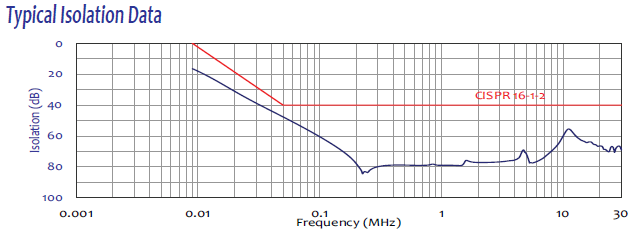
What insertion loss and isolation does the LI-3P-2100 provide across 9 kHz to 30 MHz?
Insertion loss decreases from less than 17 dB at 9 kHz to less than 11 dB at 150 kHz, remaining below 11 dB through 30 MHz. Isolation increases from greater than 0 dB at 9 kHz to greater than 40 dB at 50 kHz, then exceeds 40 dB through 30 MHz — meeting all CISPR 16-1-2 V-network requirements and ensuring facility mains noise does not contaminate EUT measurements at any frequency in the band.
How does a complete 100 A three-phase V-AMN conducted emissions test setup look in a real EMC test environment?
The LI-3P-2100 is positioned on a conductive ground plane and bonded via the unpainted mounting plate. A three-phase supply connects to the mains input using the 100A rated connectors. The EUT connects to the EUT output port. A 50Ω N-Type coaxial cable connects the RF measurement port to an EMI receiver. The RLI V2.0 fiber optic cable exits the shielded room through a waveguide penetration. Cooling fans are activated via the rear panel switch before the EUT is energized to rated load. The operator then runs sequential 9 kHz to 30 MHz sweeps on L1, L2, L3, and Neutral from the external control station.
In which specific industry sectors and test programs is the LI-3P-2100 most applicable?
The LI-3P-2100 is most applicable in EV DC fast charging qualification labs testing chargers at 50 kW and above, renewable energy inverter test facilities for utility-scale solar and wind systems, heavy industrial automation labs testing high-power servo drive stacks, battery energy storage system (BESS) converter test programs, industrial electrolyzer and hydrogen production equipment labs, data center power infrastructure qualification programs, and military and aerospace ground support power equipment test environments.
What are the earth bonding requirements for the LI-3P-2100 and what hazards arise from inadequate grounding?
The unpainted mounting plate must be bonded to the conductive ground plane with a low-impedance metal-to-metal connection. At 100 A per phase, leakage currents through the chassis can create a serious shock hazard if the earth bond is absent or high-impedance. Inadequate grounding also disrupts the CISPR 16-1-2 impedance reference, invalidating all measurements. In test facilities with non-conductive raised floors, a dedicated low-impedance bonding conductor from the mounting plate directly to the building earth bus must be installed before energizing.
What connector types and current ratings are used on the LI-3P-2100 power ports?
The LI-3P-2100 uses color-coded 100A rated receptacle and plug connectors on both the mains input and EUT output ports, with five positions for L1, L2, L3, Neutral, and Protective Earth. The RF measurement port uses a 50Ω N-Type female connector. Optional coaxial adapters (LI-3P-XXXX-ADA with LI-3P-ADA_PP100A or LI-3P-ADA_PS100A) are available for non-standard cable configurations.
How is the LI-3P-2100 calibrated and what accreditation options are available?
Every LI-3P-2100 is individually calibrated per CISPR 16-1-2 and ANSI C63.4. Full calibration data across 9 kHz to 30 MHz is supplied with each unit along with a certificate of calibration. ISO 17025 accredited calibration is available upon request for laboratories requiring recognized third-party traceability documentation.
What is the physical footprint and weight of the LI-3P-2100 and what site preparation does this require?
The LI-3P-2100 measures 36.18″ D × 31.10″ W × 17.36″ H and weighs 184.64 lbs (83.75 kg), with a shipping weight of 298.50 lbs (135.40 kg). Laboratories must plan for sufficient conductive ground plane area, a professional rigging or material handling process for installation, adequate three-phase supply infrastructure capable of delivering 100 A at the test facility supply voltage, and sufficient ventilation clearance around the top-cover exhaust outlets.
How does the LI-3P-2100 complete the LI-3P-2x series and how should laboratories choose between the four models?
The LI-3P-2x series covers four current tiers: LI-3P-216 at 16 A, LI-3P-232 at 32 A, LI-3P-263 at 63 A, and LI-3P-2100 at 100 A per phase. All share the same V-AMN topology, 9 kHz to 30 MHz range, CISPR 16-1-2 and ANSI C63.4 compliance, bypassable transient limiter with 5 dB pads, and RLI V2.0 remote switching. Select the lowest-rated model whose current capacity comfortably exceeds the EUT rated current to minimize physical size and cost while maintaining full compliance capability.
How do the LI-3P-2x series models compare to the LI-3P-1x series and when should each be specified?
The LI-3P-1x series uses a standard 50 μH network from 150 kHz to 30 MHz with a non-bypassable transient limiter, appropriate when the product standard requires only the basic 50 μH LISN method. The LI-3P-2x series uses the V-AMN 50/250 μH +5Ω network from 9 kHz to 30 MHz with a bypassable transient limiter including 5 dB attenuation pads, required when the standard mandates a V-network method or when the EUT generates significant disturbance content below 150 kHz. The correct series is determined by reviewing which LISN type the applicable product standard references in its conducted emissions measurement procedure.
How is the LI-3P-2100 used when performing V-network conducted emissions testing on a 70 kW three-phase DC ultra-fast EV charging station?
A 70 kW three-phase DC ultra-fast EV charging station drawing up to 100 A per phase from a 400 V Wye supply is one of the highest-demand EV charging products tested with the LI-3P-2100. With the charger delivering maximum DC output to a programmable load, V-network sweeps from 9 kHz to 30 MHz on all four conductors capture the harmonic content from the power factor correction and DC-DC converter stages switching at 20 to 80 kHz. The 9 kHz starting frequency is critical for CE marking and compliance with energy infrastructure regulations in multiple jurisdictions.
What is a real-world use case for the LI-3P-2100 in testing utility-scale three-phase battery energy storage system inverters at an accredited EMC laboratory?
Utility-scale BESS power conversion units drawing up to 100 A per phase are increasingly subject to V-network requirements from grid interconnection standards. With the BESS connected to a battery bank or high-capacity battery simulator, V-network sweeps from 9 kHz to 30 MHz are performed in charging, discharging, and frequency-response operating modes. Grid services functions cause the inverter to modulate output power at 1 to 10 Hz, which can excite resonances in the AC filter and produce time-varying conducted emissions across the V-network measurement band that must be captured in all operating modes.
How is the LI-3P-2100 used during type approval testing of a large three-phase photovoltaic central inverter for European grid connection certification?
Large three-phase PV central inverters rated at 50 to 100 kW drawing up to 100 A per phase require type approval testing combining EN 61000-3-12 harmonic current assessment and CISPR 11 conducted emissions evaluation. With a high-current DC source at simulated maximum power point conditions, V-network sweeps from 9 kHz to 30 MHz allow the laboratory to characterize AC-side emissions across the complete relevant frequency range in a single test configuration. The type approval certificate incorporating these results enables grid connection in EU member states.
How do manufacturers of electrolysis equipment for green hydrogen production use the LI-3P-2100 during EMC qualification?
PEM and alkaline electrolysis systems use large three-phase rectifiers drawing up to 100 A per phase for DC water-splitting current. These switched-mode rectifiers generate significant conducted emissions in the 9 kHz to 150 kHz range from their switching frequency and harmonics. Manufacturers use the LI-3P-2100 to characterize the rectifier’s conducted emission profile and size the input-side EMI filter. The V-AMN network starting at 9 kHz is mandatory here because the primary emissions fall in the sub-150 kHz band that a standard 50 μH LISN would miss entirely.
What is a typical scenario where the LI-3P-2100 is used to resolve a V-network conducted emissions failure before an overseas customer acceptance test?
A manufacturer discovers during final in-house verification with the LI-3P-2100 that V-network emissions exceed the agreed limit by 8 dB at 45 kHz on two conductors. With the LI-3P-2100 still connected to the energized EUT, the EMC engineer systematically tests additional common-mode filter stages, measuring the change at 45 kHz after each addition. After two iterations, a common-mode choke providing 12 dB attenuation at 45 kHz brings emissions 4 dB below the limit on all conductors. A complete V-network sweep from 9 kHz to 30 MHz confirms no other frequency was adversely affected. The corrected system is incorporated into the production build shipped to the overseas customer, avoiding a failed customer acceptance test and its associated project delays.

Quote Request
Other EMC Test Equipment
- Absorbing Clamps
- Antenna Kits
- Antenna Masts - Automated and Manual
- Antennas
- Bulk Current Injection probes
- CDNs - Coupling Decoupling Network
- Comb Generators
- Conducted Immunity Test Systems
- Current Monitor Probes
- Current Probe Calibration Fixtures
- EM Clamps
- Feed Through Capacitor
- ISNs - Impedance Stabilization Network
- LISNs - Single Phase
- LISNs - TEMPEST
- LISNs - Three Phase
- Magnetic Field Generator
- Near Field Probes
- Power Amplifiers
- Pre-compliance Emissions Test Systems
- Preamplifiers
- Spectrum Analyzers
- Surge Generators
- System Controllers
- Transient Limiters
- Tripods For EMC
- Turntables