
LISN for DO-160, FAA, MIL-STD 461, CISPR 25 & 16-1-2
-
LI-325C Line Impedance Stabilization Network:
-
The LI-325C LISN operates over a frequency range of 10 kHz to 400 MHz.
-
It is fully compliant with RTCA DO-160, FAA, and MIL-STD 461 standards.
-
The unit provides stable impedance and isolates the EUT from power source effects.
-
It ensures accurate and repeatable power line conducted emissions testing.
-
Each LI-325C includes a pair of single-conductor networks for flexible system use.
-
A second pair can be added for compatibility with three-phase power systems.
-
Air-core inductors prevent saturation and permeability variations.
-
It uses Superior Electric SUPERCON® shrouded sockets for power connections.
-
Color-coded plugs for mains and EUT wiring are included for easy setup.
-
The unpainted mounting plate ensures proper grounding to earth.
-
Each unit is individually calibrated with supplied impedance and loss data.
-
Calibration includes a certificate for RTCA DO-160, FAA, and MIL-STD 461 compliance.
-
The LISN is backed by a three-year warranty from Com-Power Corporation.
Features
- ▸ Multi-standard 3x Series 5 µH LISN, 25 A rated — the bench-level workhorse of the 3x Series for avionics, automotive, and military testing programs that need the lowest-current member of the 3x lineup.
- ▸ Wide 10 kHz to 400 MHz frequency range — covers DO-160 Section 21, FAA conducted emissions, MIL-STD 461 CE101/CE102, CISPR 25 automotive, and CISPR 16-1-2 commercial bands in a single LISN.
- ▸ Multi-standard compliance: DO-160 / FAA / MIL-STD 461D / CISPR 25 / CISPR 16-1-2 — one LISN for both military/aerospace and commercial/automotive programs, eliminating the need to swap LISNs between test standards.
- ▸ 5 µH air-core inductor — lower inductance enables accurate high-frequency impedance stabilization to 400 MHz; air-core construction prevents magnetic saturation across all load currents up to 25 A.
- ▸ Insertion loss < 0.3 dB (150 kHz–30 MHz) — exceptionally low insertion loss across the CISPR conducted emissions band ensures measured disturbance voltages accurately represent EUT emissions.
- ▸ 25 A AC / 17 A DC current rating, 270 VAC / 380 VDC voltage rating — covers avionics line-replaceable units (LRUs), cockpit displays, flight management computers, automotive ECUs, and bench-level low-to-medium power airborne and vehicular electronics.
- ▸ Superior Electric SUPERCON® shrouded sockets — safe shrouded design guards against accidental contact with live conductors; matching color-coded plugs included for mains and EUT wiring.
- ▸ 50 Ω N-type female RF connector — standard interface for direct connection to EMI receivers and spectrum analyzers across the full 10 kHz to 400 MHz range.
- ▸ Unpainted mounting plate for low-impedance ground bond — metal-to-metal bonding to the test setup ground plane is essential for valid measurements at high frequencies and personnel safety.
- ▸ 3-phase ready — a second LI-325C pair extends the setup to 3-phase Wye or Delta power systems for testing 3-phase aerospace, military, and automotive equipment.
- ▸ Individually NIST-traceable calibrated — impedance, phase, isolation, and insertion loss data shipped with each unit. ISO 17025 accredited calibration available on request.
- ▸ Three-year standard warranty — backed by manufacturer support.
Specifications
| Model | LI-325C |
|---|---|
| Series | 3x Series — Multi-standard 5 µH, single-conductor pair |
| Specification | DO-160 / FAA / MIL-STD 461D / CISPR 25 / CISPR 16-1-2 |
| Application | Avionics, automotive ECU, military electronics conducted emissions tests |
| Frequency Range | 10 kHz – 400 MHz |
| Inductors | 5 µH (air-core) |
| Current Rating | 25 Amperes AC, 17 Amperes DC |
| Voltage Rating | 270 VAC (Line to Ground), 380 VDC |
| RF Connector | 50 Ohms N-type (female) |
| Insertion Loss | < 0.3 dB (150 kHz – 30 MHz); see graph for full range |
| Mains & EUT Connections | Superior Electric SUPERCON® shrouded sockets |
| Calibration | Individual, NIST-traceable; ISO 17025 accredited available on request |
| Warranty | Three-year standard warranty |
All values are typical, unless specified. Ships as a pair of separately housed networks. All specifications subject to change without notice.
🔍 Not Sure This Is The Right LISN?
Compare all 25 Com-Power LISN models side-by-side with our interactive selection tool. Filter by current, voltage, frequency, and standards to find your perfect match.
Compare All LISN Models →LI-325C DO-160 / MIL-STD-461 Single-Phase LISN FAQs
What is the LI-325C and what type of testing is it designed for?
The LI-325C is a single-conductor, 50Ω, 5 μH Line Impedance Stabilization Network (LISN) designed for power-line conducted emissions compliance testing per RTCA DO-160 and MIL-STD-461. It provides a defined, stable impedance on the power line, isolates the EUT from power source influences, and couples disturbance voltages to the RF measurement port. The LI-325C is used for avionics and aerospace equipment certification per DO-160 and for military equipment conducted emissions testing per MIL-STD-461, covering aircraft avionics, airborne power supplies, UAV electronics, and military vehicle and shipboard subsystems.
What standards does the LI-325C comply with and what do those standards require?
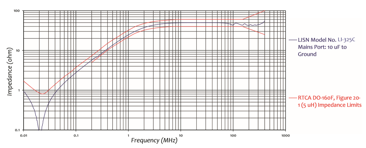
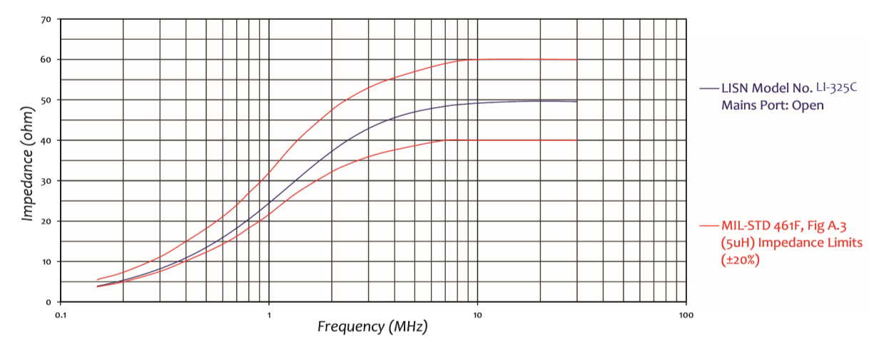
The LI-325C is compliant with RTCA DO-160 (Section 21, conducted emissions for airborne equipment) and MIL-STD-461D/E/F/G (CE101/CE102 conducted emissions for military equipment). The 5 μH network topology is the LISN configuration specified by both standards, distinguishing it from the 50 μH V-network used in commercial CISPR 16-1-2 testing.
What is the frequency range of the LI-325C and what is the significance of 10 kHz to 400 MHz coverage?
The LI-325C covers 10 kHz to 400 MHz — covering both the DO-160 Section 21 conducted emissions range and the MIL-STD-461 CE102 range in a single LISN. The 400 MHz upper limit ensures coverage for modern avionics testing requirements including DO-160G and later, where conducted emissions measurements extend to higher frequencies than older DO-160 revisions.
Why does the LI-325C use a 5 μH inductor instead of the 50 μH used in CISPR 16-1-2 commercial LISNs?
The 5 μH LISN network topology is specified by both RTCA DO-160 and MIL-STD-461 for aerospace and military conducted emissions testing. Aircraft and military power systems use higher-frequency power distribution (typically 400 Hz) and different power system impedance environments than commercial 50/60 Hz systems. The 5 μH network reaches its 50 Ω asymptotic impedance at lower frequencies than the 50 μH network, appropriate for these environments. Using a 50 μH commercial LISN for DO-160 or MIL-STD-461 testing would produce non-compliant measurements.
What is the current rating of the LI-325C and what class of aerospace and defense equipment does it support?
The LI-325C is rated at 25 A AC and 17 A DC. This supports aircraft cockpit displays, communication and navigation radios, airborne radar signal processors, flight management computers, aircraft lighting and power distribution units, military vehicle electronic subsystems, vehicle-mounted communications, portable military electronics, and UAV/drone electronic payloads. Most individual avionics LRUs and military electronic subsystems draw less than 25 A.
What is the voltage rating of the LI-325C and what aerospace and military power systems does it accommodate?
The LI-325C is rated at 270 VAC line to ground and 380 VDC. This covers 115 VAC 400 Hz aircraft power, 28 VDC, and 270 VDC high-voltage DC bus systems common in aircraft and military platforms. For higher-voltage systems (480 VAC or 600 VDC), the LI-350 (50 A, 480 VAC / 600 VDC) is the appropriate alternative.
The LI-325C is sold as a pair of networks. Why is a pair required and how are they connected?
Conducted emissions compliance requires a LISN in series with each current-carrying conductor simultaneously (Line and Neutral, or positive and negative DC). One LI-325C is installed in each conductor. The measurement is performed one conductor at a time with the inactive LISN RF port terminated at 50 Ω. For three-phase systems, a second LI-325C pair accommodates Phase B, Phase C, and Neutral.
What type of connectors does the LI-325C use at the mains and EUT ports?
The LI-325C uses Superior Electric SUPERCON® shrouded sockets at both mains and EUT ports, with color-coded plugs for mains and EUT wiring included. The shrouded design protects against accidental contact with live conductors, and color coding prevents polarity errors during connection.
Why is the mounting plate of the LI-325C left unpainted and what grounding is required?
The unpainted mounting plate enables a low-impedance metal-to-metal bond to the bonding plane required by DO-160 and MIL-STD-461 test setups. LISN internal capacitors create leakage current paths between power line conductors and the chassis that must return to the bonding plane. Without a verified low-impedance ground bond, both measurement accuracy and personnel safety are compromised.
What RF connector does the LI-325C use and what should be connected to the RF measurement port?
The LI-325C uses a 50 Ω N-type female RF connector, connecting via 50 Ω coaxial cable to an EMI receiver configured per DO-160 Section 21 or MIL-STD-461. The inactive LISN RF port must be terminated at 50 Ω during measurements. Com-Power recommends a Transient Limiter between the RF port and the receiver.
What insertion loss does the LI-325C provide and how is it applied in post-processing?
The LI-325C provides insertion loss below 0.3 dB from 150 kHz to 30 MHz; insertion loss increases below 150 kHz consistent with the 5 μH network characteristic. The insertion loss correction from individual calibration data must be added to raw receiver readings at each frequency point to obtain actual disturbance voltages, which are then compared against DO-160 Section 21 or MIL-STD-461 CE102 limit lines.
How is the LI-325C individually calibrated and what calibration data is supplied?
Every LI-325C is individually calibrated per RTCA DO-160 and MIL-STD-461. Impedance and insertion loss data across the full 10 kHz to 400 MHz range are supplied with a certificate of calibration. Individual calibration verifies the impedance characteristic against DO-160 and MIL-STD-461 tolerance limits and provides frequency-dependent insertion loss corrections for accurate compliance measurements.
What is the warranty coverage for the LI-325C?
The LI-325C carries a three-year warranty from Com-Power Corporation. Periodic recalibration on a one- or two-year interval is recommended to maintain traceability for DO-160 and MIL-STD-461 compliance programs, particularly for laboratories operating under ISO/IEC 17025 or where the program authority requires calibration documentation.
What are the physical dimensions and weight of the LI-325C?
Each LI-325C network measures 11.8 x 5.7 x 5.3 inches (30 x 14.5 x 13.5 cm) and weighs 5 lbs (2.2 kg). The LI-325C is more compact and lighter than 50 μH commercial LISNs because the 5 μH air-core inductors are physically smaller. A complete single-phase installation requires space for both units on the bonding plane with cable routing to the power source, EUT, and EMI receiver.
How does the LI-325C differ from the LI-400C, and how should a test engineer choose between them for MIL-STD-461 testing?
The LI-325C uses a 5 μH network, covers 10 kHz to 400 MHz, and is compliant with both DO-160 and MIL-STD-461. The LI-400C uses a 50 μH network, covers 10 kHz to 10 MHz, and is compliant with MIL-STD-461 only. Check the specific MIL-STD-461 test plan and contract requirements — both 5 μH and 50 μH LISNs appear in MIL-STD-461 depending on the revision and applicable CE test method. The LI-325C is required when the program specifies the 5 μH MIL-STD-461 network or DO-160 compliance.
How does the LI-325C compare to the LI-350 and when should the LI-350 be used instead?
Both models use a 5 μH network covering 10 kHz to 400 MHz. The LI-325C is rated at 25 A AC, 270 VAC, 380 VDC. The LI-350 is rated at 50 A, 480 VAC (50–400 Hz), 270 VAC (800 Hz), 600 VDC. Choose the LI-350 when the EUT draws more than 25 A, when the platform uses voltages exceeding 270 VAC or 380 VDC, or when 800 Hz high-frequency military power is involved.
What types of equipment cannot be tested with the LI-325C?
The LI-325C is not suitable for: equipment exceeding 25 A AC or 17 A DC (use LI-350); power systems exceeding 270 VAC or 380 VDC (use LI-350); commercial CISPR 16-1-2 / ANSI C63.4 testing (use 50 μH LISNs such as LI-125C or LI-150C); CISPR 25 automotive testing (use LI-550C); or MIL-STD-461 CE102 programs specifically requiring the 50 μH network topology (use LI-400C or LI-4100).
How is the LI-325C used in a DO-160G Section 21 conducted emissions test on an aircraft avionics LRU?
The LI-325C pair is bonded to the EMC test facility bonding plane. The 115 VAC 400 Hz aircraft power source connects to the mains inputs. The avionics LRU connects to the EUT outputs. An EMI receiver configured for DO-160 Section 21 connects to the Line LISN RF port via a Transient Limiter; the Neutral RF port is terminated at 50 Ω. Conducted emissions are measured on Line and Neutral alternately, and results are compared against DO-160 Section 21 limits for the equipment’s power category, with LI-325C calibration insertion loss corrections applied.
What does a MIL-STD-461 CE102 test setup using the LI-325C look like for a military vehicle electronic subsystem?
The LI-325C pair is bonded to the MIL-STD-461 reference bonding plane. The military vehicle power supply (28 VDC or 270 VDC) connects to the mains inputs. The mains port is left open (no external impedance) per the MIL-STD-461 5 μH LISN configuration. CE102 sweeps from 10 kHz to 10 MHz are performed on positive and negative DC bus conductors alternately, with insertion loss corrections applied, and results compared against MIL-STD-461F CE102 limits.
How is the LI-325C applied when testing UAV avionics for both DO-160 and MIL-STD-461 compliance?
UAV avionics often require both civil airworthiness certification under DO-160 and defense procurement compliance under MIL-STD-461. The LI-325C’s compliance with both standards means a single LISN supports both test programs without changing hardware. The test engineer configures the EMI receiver and test procedure per the applicable standard for each session, applying appropriate limit lines and insertion loss corrections. This dual-standard capability reduces both equipment cost and test scheduling complexity for UAV programs requiring both civil and military EMC compliance.
How does an aerospace EMC laboratory use the LI-325C for developmental testing of a new aircraft power conversion unit?
During design verification of a new aircraft power conversion unit, the LI-325C provides the standardized 5 μH measurement platform for DO-160-valid pre-qualification data. The unit is powered from a simulated 115 VAC 400 Hz source through the LI-325C pair at rated output load. Conducted emissions scans from 10 kHz to 400 MHz on both Line and Neutral are compared against DO-160 Section 21 limits. Early identification of non-compliant frequency bands allows the design team to implement EMI filtering or switching frequency adjustments before formal qualification testing, significantly reducing the risk of a late-stage qualification failure.


Quote Request
Other EMC Test Equipment
- Absorbing Clamps
- Antenna Kits
- Antenna Masts - Automated and Manual
- Antennas
- Bulk Current Injection probes
- CDNs - Coupling Decoupling Network
- Comb Generators
- Conducted Immunity Test Systems
- Current Monitor Probes
- Current Probe Calibration Fixtures
- EM Clamps
- Feed Through Capacitor
- ISNs - Impedance Stabilization Network
- LISNs - Single Phase
- LISNs - TEMPEST
- LISNs - Three Phase
- Magnetic Field Generator
- Near Field Probes
- Power Amplifiers
- Pre-compliance Emissions Test Systems
- Preamplifiers
- Spectrum Analyzers
- Surge Generators
- System Controllers
- Transient Limiters
- Tripods For EMC
- Turntables