
LISN 25 Amps For CISPR 16 & ANSI C63.4
Com-Power LI-125C LISN
-
The LI-125C operates over a frequency range of 150 kHz to 30 MHz.
-
Fully compliant with CISPR 16-1-2 and ANSI C63.4 standards.
-
Uses air-core inductors to eliminate core saturation and maintain stability.
-
Includes individual calibration with NIST traceable certificate.
-
Comes with a standard three-year warranty.
Description & Application
-
The LI-125C provides a stable, defined impedance for power line conducted emissions testing.
-
It isolates the equipment under test (EUT) from the power source to ensure repeatable measurements.
-
Suitable for use in single-phase, dual-phase, and DC systems, with optional extension for 3-phase systems.
Construction
-
Includes a pair of separately housed, single-conductor networks.
-
Equipped with Superior Electric SUPERCON® shrouded sockets and matching plugs for safe, secure connections.
-
Built with an unpainted mounting plate for effective grounding, crucial for high-leakage current scenarios.
Transient Protection
-
A transient limiter is recommended for added protection and improved measurement quality, available from Com-Power.
Calibration
-
Each unit is individually calibrated per CISPR 16-1-2 and ANSI C63.4 standards.
-
Supplied with calibration certificate and detailed performance data (impedance, phase, isolation, insertion loss).
Features
- ▸ Single-conductor 1x Series LISN, separately housed pair — one network for the Line conductor, one for the Neutral; each unit individually calibrated. Industry-standard configuration for hardwired commercial conducted emissions testing.
- ▸ 150 kHz to 30 MHz frequency range — covers the full CISPR Band B / commercial conducted emissions band for FCC Part 15, CISPR 22 / 32, EN 55022 / 55032 product certification testing.
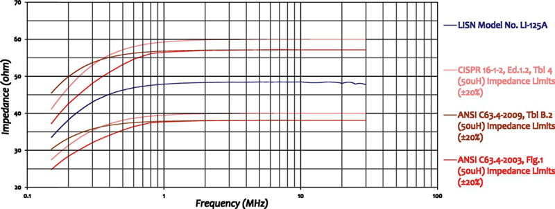
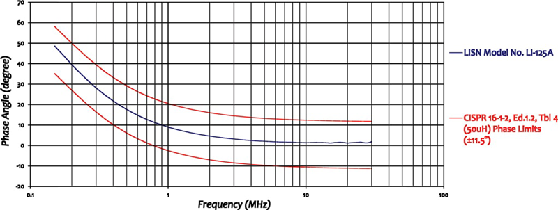
- ▸ Fully compliant with CISPR 16-1-2 and ANSI C63.4 — the 50 Ω / 50 µH V-network is calibrated to both standards, accepted by accredited EMC test laboratories worldwide.
- ▸ 25 A AC / 17 A DC current rating, 270 VAC / 380 VDC voltage rating — covers desktop computers, monitors, printers, network equipment, audio/video products, lighting up to ~6 kW, and small-to-mid power supplies and motor drives.
- ▸ 50 µH air-core inductors prevent saturation — air-core construction keeps inductance constant at all currents up to 25 A, ensuring the defined LISN impedance remains stable and measurements stay calibrated.
- ▸ Superior Electric SUPERCON® shrouded sockets — safe shrouded design guards against accidental contact with live conductors; matching color-coded plugs included for mains and EUT wiring, ideal for hardwired equipment without standard AC plugs.
- ▸ 50 Ω N-type female RF connector — standard interface for direct connection to EMI receivers and spectrum analyzers; insertion loss < 0.5 dB and isolation > 40 dB across 150 kHz to 30 MHz.
- ▸ External transient limiter recommended — pair with the Com-Power LIT-153A or similar for impedance matching, out-of-band filtering, and EMI receiver input protection from EUT switching transients.
- ▸ Unpainted mounting plate for low-impedance ground bond — metal-to-metal bonding to the test setup ground plane is essential for valid measurements and personnel safety; supports the high leakage currents inherent to LISN operation.
- ▸ 3-phase ready — a second LI-125C pair extends the setup to 3-phase Wye or Delta power systems.
- ▸ Individually NIST-traceable calibrated — impedance, phase, isolation, and insertion loss data shipped with each unit. ISO 17025 accredited calibration available on request.
- ▸ Three-year standard warranty — backed by manufacturer support.
Specifications
| Model | LI-125C |
|---|---|
| Series | 1x Series — Single-conductor pair, separately housed |
| Specification | CISPR 16-1-2 / ANSI C63.4 |
| Application | Power Line conducted emissions tests |
| Frequency Range | 150 kHz – 30 MHz |
| Inductors | 50 µH (air-core) |
| Current Rating | 25 Amperes AC, 17 Amperes DC |
| Voltage Rating | 270 VAC (Line to Ground), 380 VDC |
| RF Connector | 50 Ohms N-type (female) |
| Insertion Loss | < 0.5 dB (150 kHz – 30 MHz) |
| Isolation | > 40 dB (150 kHz – 30 MHz) |
| Mains & EUT Connections | Superior Electric SUPERCON® shrouded sockets |
| Dimensions (each network) | 13 × 7 × 7 in (33 × 17.7 × 17.7 cm) |
| Weight (each network) | 6 lbs (2.7 kg) |
| Calibration | Individual, NIST-traceable; ISO 17025 accredited available on request |
| Warranty | Three-year standard warranty |
All values are typical, unless specified. Ships as a pair of separately housed networks. All specifications subject to change without notice.
🔍 Not Sure This Is The Right LISN?
Compare all 25 Com-Power LISN models side-by-side with our interactive selection tool. Filter by current, voltage, frequency, and standards to find your perfect match.
Compare All LISN Models →LI-125C CISPR 16-1-2 / ANSI C63.4 Single-Phase LISN FAQs
What is the LI-125C and what type of testing is it designed for?
The LI-125C is a single-conductor, 50Ω, 50 μH Line Impedance Stabilization Network (LISN) designed for power-line conducted emissions compliance testing per CISPR 16-1-2 and ANSI C63.4. It provides a defined, stable impedance on the power line under test, isolates the EUT from power source influences, and couples disturbance voltages to the RF measurement port. The LI-125C serves commercial product compliance testing across consumer electronics, IT equipment, industrial equipment, and lighting products requiring FCC Part 15, CISPR 22, EN 55032, or similar certification.
What standards does the LI-125C comply with and what do those standards require?
The LI-125C is fully compliant with CISPR 16-1-2 (specifying LISN electrical characteristics for conducted emissions measurements) and ANSI C63.4 (the American National Standard for radio-noise emissions measurement for FCC compliance). Compliance with both means the LI-125C is accepted by accredited EMC test laboratories worldwide for product certification.
What is the frequency range of the LI-125C and why does conducted emissions testing start at 150 kHz?
The LI-125C covers 150 kHz to 30 MHz. Commercial conducted emissions testing begins at 150 kHz — the lower boundary defined by CISPR 16-1-2 and ANSI C63.4 for the standard 50 μH V-network LISN. The 30 MHz upper limit marks the boundary above which emissions are characterized as radiated. Products must demonstrate compliance across the full 150 kHz to 30 MHz range.
What is the current rating of the LI-125C and what class of products does it support?
The LI-125C is rated at 25 A AC and 17 A DC. This covers desktop computers, monitors, printers, network equipment, audio-visual products, lighting up to approximately 6 kW, small-to-mid industrial power supplies, and motor drives for HVAC and appliance applications drawing up to 25 A at 120 V (3 kW) or 240 V (6 kW).
What is the voltage rating of the LI-125C and what power systems does it support?
The LI-125C is rated at 270 VAC line-to-ground at 50–60 Hz and 380 VDC. This covers 120 V single-phase (North America), 230–240 V single-phase (Europe, Asia), and DC voltages up to 380 V. For dual-phase 240 V split-phase systems, one unit is installed in each current-carrying conductor.
How does the LI-125C achieve its defined impedance and why is a 50 μH air-core inductor used?
A 50 μH inductor in series with the power line conductor, combined with a capacitor and resistor network, creates the defined 50 Ω termination at the RF port. Air-core inductors prevent magnetic saturation — a ferromagnetic core would saturate at elevated currents, causing inductance to collapse below 50 μH and invalidating the LISN impedance. Air-core inductors maintain a constant 50 μH at all currents up to the 25 A rating.
The LI-125C is sold as a pair of networks. Why is a pair required and how are they connected?
A single-phase AC system has two current-carrying conductors (Line and Neutral), and compliance testing requires a LISN in series with each conductor simultaneously. One unit is installed in the Line conductor and one in the Neutral. The measurement is performed one conductor at a time; the inactive LISN RF port is terminated at 50 Ω. For three-phase systems, a second LI-125C pair accommodates the additional phase conductors.
What type of connectors does the LI-125C use at the mains and EUT ports?
The LI-125C uses Superior Electric SUPERCON® shrouded sockets at both mains and EUT ports. The shrouded design guards against accidental contact with live conductors. Color-coded plugs for mains and EUT wiring are included with the unit, maintaining correct polarity and preventing orientation errors.
Why is the mounting plate of the LI-125C left unpainted and what grounding is required?
The unpainted mounting plate enables a low-impedance metal-to-metal bond to the test setup ground plane. This is essential because LISN internal capacitors carry leakage currents between power line conductors and the chassis. Without a solid earth ground, these currents create measurement errors and safety hazards. The ground plane must be bonded to protective earth per applicable standard requirements.
What RF connector does the LI-125C use and what should be connected to the RF measurement port?
The LI-125C uses a 50 Ω N-type female RF connector, connecting via 50 Ω coaxial cable to an EMI receiver or spectrum analyzer. The inactive LISN RF port must be terminated with 50 Ω during measurements. Com-Power recommends inserting a Transient Limiter between the RF port and the instrument for impedance matching, out-of-band attenuation, and transient protection.
What insertion loss and isolation does the LI-125C provide and why do these parameters matter?
The LI-125C provides insertion loss below 0.5 dB and isolation above 40 dB across 150 kHz to 30 MHz. Low insertion loss ensures measured disturbance voltages accurately represent actual EUT emissions. High isolation (40+ dB) attenuates facility power line noise before it reaches the measurement port, preventing external noise from contaminating EUT results.
How is the LI-125C individually calibrated and what calibration data is supplied?
Every LI-125C is individually calibrated per CISPR 16-1-2 and ANSI C63.4. Impedance, phase, isolation, and insertion loss data for the specific unit are supplied along with a certificate of calibration, enabling precise insertion loss corrections during compliance testing and accounting for unit-to-unit component variations.
What is the warranty coverage for the LI-125C?
The LI-125C carries a three-year warranty from Com-Power Corporation. As a passive instrument, its service life is long under normal laboratory operating conditions. Periodic recalibration on a one- or two-year interval is recommended to maintain measurement traceability.
What are the physical dimensions and weight of the LI-125C?
Each LI-125C network measures 13 x 7 x 7 inches (33 x 17.7 x 17.7 cm) and weighs 6 lbs (2.7 kg). A complete single-phase installation requires bench space for both units on the ground plane with cable routing to mains, EUT ports, and the EMI receiver. Units should be positioned as close as possible to the EUT power input to minimize unprotected wiring length between the LISN EUT port and the EUT.
What is a Transient Limiter and why does Com-Power recommend one with the LI-125C?
A Transient Limiter is inserted between the LISN RF port and the EMI receiver. Com-Power recommends one for: impedance matching between the 50 Ω LISN output and receiver input; attenuation of out-of-band emissions below 150 kHz and above 30 MHz that could overload the receiver; and transient protection against voltage spikes from EUT switching events that could damage sensitive receiver input stages.
How does the LI-125C compare to other Com-Power single-phase CISPR 16-1-2 / ANSI C63.4 LISNs?
The LI-125C (25 A AC), LI-150C (50 A AC), and LI-1100C (100 A AC, forced-air cooling) form the single-conductor CISPR 16-1-2 / ANSI C63.4 range, all sharing 150 kHz to 30 MHz, 50 Ω N-type RF connector, 50 μH air-core inductors, and individual calibration. Select the lowest-rated model accommodating the EUT current. The LI-220C and LIN-120C are dual-conductor models with both Line and Neutral networks in a single enclosure — more compact for lower-current products.
What types of equipment cannot be tested with the LI-125C?
The LI-125C is not suitable for: equipment exceeding 25 A AC or 17 A DC (use LI-150C or LI-1100C); equipment requiring DO-160 or MIL-STD-461 testing (use LI-325C, LI-350, LI-400C, or LI-4100); automotive/vehicle component testing under CISPR 25 (use LI-550C); or three-phase equipment without a second pair (use two LI-125C pairs or a dedicated LI-3P series LISN).
How is the LI-125C used when performing conducted emissions pre-compliance testing on a switching power supply during product development?
During switching power supply development, the LI-125C is set up on a bench ground plane with the supply connected to the EUT port and an electronic load at rated current. A spectrum analyzer replaces the formal EMI receiver for cost-effective screening. Line and Neutral are measured alternately with the inactive port terminated at 50 Ω, and results are compared against applicable limit lines. The LI-125C’s calibrated impedance ensures bench pre-compliance results closely predict formal laboratory outcomes, reducing costly re-tests.
What is the procedure for setting up the LI-125C for a formal CISPR 22 / EN 55032 conducted emissions test on an IT product?
For a formal EN 55032 test, the LI-125C pair is bonded to the facility reference ground plane. The mains connects to the LISN mains inputs; the IT product connects to the EUT outputs. A 50 Ω cable connects the Line LISN RF port through a Transient Limiter to the EMI receiver; the Neutral RF port is terminated at 50 Ω. The receiver uses a CISPR quasi-peak detector scanning 150 kHz to 30 MHz. After the Line scan, connections are swapped to measure Neutral. Both results are compared against EN 55032 Class A or Class B limits.
How does an EMC engineer use the LI-125C to investigate a conducted emissions failure on a motor drive?
With the motor drive at worst-case load through the LI-125C, a real-time analyzer correlates failing frequencies with switching frequency harmonics. The engineer varies switching frequency, adds or modifies differential-mode or common-mode EMI filter components, and observes immediate effects on the spectrum. The LI-125C’s stable defined impedance ensures filter changes produce predictable, reproducible measurement results rather than artifacts of a non-standardized source impedance.
In what DC power system applications is the LI-125C used and how does the DC configuration differ from AC?
The LI-125C’s 380 VDC / 17 A DC rating supports conducted emissions testing of 24 VDC and 48 VDC industrial power distribution systems, 380 VDC data center power distribution, telecom equipment on −48 VDC central office supplies, and EV charging infrastructure DC bus components. One LI-125C is placed in series with the positive DC bus conductor and one in the negative DC bus conductor. The air-core inductors carry DC current without saturation and the 150 kHz to 30 MHz impedance characteristic is identical to AC configurations.


Quote Request
Other EMC Test Equipment
- Absorbing Clamps
- Antenna Kits
- Antenna Masts - Automated and Manual
- Antennas
- Bulk Current Injection probes
- CDNs - Coupling Decoupling Network
- Comb Generators
- Conducted Immunity Test Systems
- Current Monitor Probes
- Current Probe Calibration Fixtures
- EM Clamps
- Feed Through Capacitor
- ISNs - Impedance Stabilization Network
- LISNs - Single Phase
- LISNs - TEMPEST
- LISNs - Three Phase
- Magnetic Field Generator
- Near Field Probes
- Power Amplifiers
- Pre-compliance Emissions Test Systems
- Preamplifiers
- Spectrum Analyzers
- Surge Generators
- System Controllers
- Transient Limiters
- Tripods For EMC
- Turntables