
Low Noise Wideband Preamplifier from 1 GHz to 6 GHz
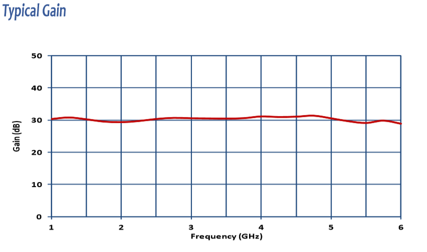
- The PAM-6000 is a battery-powered low-noise microwave preamplifier covering 1 GHz to 6 GHz with 30 dB gain — the focused-band preamp for sub-6 GHz radiated EMI testing.
- Noise figure < 5.7 dB max with ±2 dB gain flatness; lowers the system noise floor for low-level emissions close to compliance limits.
- Covers the entire FCC Part 15 / CISPR 32 / EN 55032 above-1-GHz radiated emissions band plus 5G FR1 sub-6 GHz for wireless device certification testing.
- Compensates for long RF cable losses in 3 m and 10 m chamber setups where microwave coax can lose 1–2 dB per meter; place at the antenna to maximize signal-to-noise.
- Pairs with double-ridged horn antennas, standard gain horns, and log-periodic antennas with antenna factors of 25–35 dB/m across the 1–6 GHz range to lift weak signals above receiver noise.
- Ideal for Wi-Fi, Bluetooth, cellular, ISM, automotive radar pre-compliance, IoT modules, and high-speed digital products; both formal compliance testing and pre-compliance debug.
- Compact form factor 7.5″ × 5″ × 3″ (9 × 13 × 7.6 cm), 2.5 lbs (1.1 kg), 50Ω N-type female connectors, 6 V NiMH rechargeable battery for noise-free operation near the antenna.
- Individually NIST-traceable calibrated; ISO 17025 calibration available on request. Three-year warranty.
Features
- ▸ Microwave EMI/EMC preamplifier covering 1 GHz to 6 GHz — bridges the 1 GHz boundary where general-purpose RF preamps end and microwave preamps begin; ideal for above-1 GHz radiated emissions testing.
- ▸ 30 dB gain with ±2 dB flatness — consistent gain across the band minimizes correction complexity and ensures emission-trend data reflects DUT behavior, not amplifier ripple.
- ▸ Low noise figure of 5.7 dB max — improves receiver sensitivity for low-level emissions close to the system noise floor in the microwave band.
- ▸ Output power +13 dBm at 1 dB compression — ensures linear operation when measuring higher-level microwave emissions without saturation distortion.
- ▸ Compensates microwave coaxial cable loss — cable losses become significant above 1 GHz, especially in 3 m and 10 m chamber setups; placing the PAM-6000 near the antenna preserves signal integrity before cable attenuation.
- ▸ Pairs with horn antennas (AHA-118A, AH-118) — ideal companion for double-ridged and standard gain horn antennas with antenna factors typically 25–35 dB/m across 1–6 GHz.
- ▸ 5G FR1 sub-6 GHz, Wi-Fi, Bluetooth, cellular emissions verification — covers the upper portion of FCC Part 15, CISPR 32 / EN 55032, and CISPR 25 automotive radiated emissions where modern wireless devices emit.
- ▸ 50Ω N-type (female) input/output connectors — standard microwave-grade interface for connection to horn antennas, log-periodic antennas, and EMI receivers.
- ▸ Battery operation — internal NiMH battery pack allows placement near the antenna in chambers where AC power is inconvenient or where conducted noise from bench supplies must be avoided.
- ▸ Compact bench-top form factor — 7.5″ × 5″ × 3″ (19 × 13 × 7.6 cm), 2.5 lbs (1.1 kg); easy to mount near the antenna or directly on chamber turntables.
- ▸ Useful for near-field probe debug at microwave frequencies — supports troubleshooting of high-speed digital circuits, RF modules, and shielded enclosures during the design phase.
- ▸ Individually calibrated, NIST-traceable — calibration data and certificate ship with each unit; ISO 17025 accredited calibration available on request.
- ▸ Three-year standard warranty — backed by manufacturer support.
Specifications
| Model | PAM-6000 |
|---|---|
| Application | EMI / EMC Measurements (microwave band, sub-6 GHz) |
| Frequency Range | 1 GHz to 6 GHz |
| Gain | 30 dB |
| Gain Flatness | ± 2 dB |
| Noise Figure | < 5.7 dB max |
| Output Power @ 1 dB Compression | +13 dBm |
| Maximum RF Input | +2 dBm |
| Maximum DC Input | 10 VDC max |
| Input/Output Impedance | 50 Ω |
| Connector Type | N-type (female) |
| Power | 6 VDC, 500 mA |
| Battery Type | 6 V NiMH (rechargeable) |
| Dimensions (L × W × H) | 7.5″ × 5″ × 3″ (19 × 13 × 7.6 cm) |
| Weight | 2.5 lbs (1.1 kg) |
| Calibration | Individually calibrated, NIST traceable; ISO 17025 accredited available on request |
| Warranty | Three-year standard warranty |
All values are typical, unless specified. All specifications are subject to change without notice.
1. What is the PAM-6000 primarily used for?
The PAM-6000 is a microwave preamplifier designed to increase measurement sensitivity during radiated EMI emissions testing in the 1 GHz to 6 GHz range. It amplifies very low-level RF signals so they can be accurately detected by an EMI receiver.
2. Why is a preamplifier essential for EMI testing above 1 GHz?
Above 1 GHz, antenna factors increase sharply and RF cable losses become significant, especially with long cable runs in chambers. Without a preamplifier, real emissions may fall below the receiver’s noise floor, leading to missed or underestimated results.
3. How can static electricity damage a microwave preamplifier like the PAM-6000?
Static electricity (ESD) can discharge directly into the highly sensitive RF input stage of a microwave preamplifier and permanently damage it. This often happens when connecting or disconnecting antennas, probes, or cables that have accumulated static charge, especially in dry environments or large chambers.
4. What practical measures help protect the PAM-6000 from static electricity damage?
To reduce ESD risk:
-
Always turn off the preamplifier before connecting or disconnecting RF cables
-
Ensure antennas, near-field probes, and cables are properly grounded before connection
-
Avoid handling RF connectors directly in low-humidity environments
-
Use static-dissipative work practices and grounding straps where possible
-
Place the preamplifier after the antenna is already positioned and stabilized
These steps help prevent sudden electrostatic discharge from reaching the preamplifier’s input circuitry.
5. Where is the PAM-6000 placed in a typical EMI measurement setup?
The PAM-6000 is typically installed between the antenna (or near-field probe) and the EMI receiver, as close to the antenna as practical. This placement boosts weak signals before they experience cable loss.
6. Which EMC test scenarios commonly use the PAM-6000?
The PAM-6000 is commonly used for radiated emissions testing above 1 GHz, including:
-
CISPR and FCC radiated emissions measurements
-
Automotive, industrial, and consumer electronics compliance testing
-
Pre-compliance scans and diagnostic measurements
7. How does the PAM-6000 differ from a power amplifier?
A power amplifier is used to generate high RF power for immunity testing, while the PAM-6000 is a measurement-side device used to amplify weak received signals. It does not drive antennas or inject RF energy into the EUT.
8. Can the PAM-6000 be used with both antennas and near-field probes?
Yes. The PAM-6000 is commonly used with microwave horn antennas for far-field measurements and can also increase sensitivity when using near-field probes during troubleshooting and diagnostics.
9. Why is gain flatness important in a microwave preamplifier?
Flat gain across frequency ensures that measurement accuracy does not vary with frequency. This reduces correction complexity and helps ensure that emission trends reflect the EUT’s behavior rather than measurement system artifacts.
10. How does the PAM-6000 help compensate for long RF cable runs?
By amplifying signals before they travel through long RF cables, the PAM-6000 offsets microwave cable attenuation, preserving signal-to-noise ratio and improving measurement repeatability.
11. Why is noise figure important in EMI measurements?
Noise figure indicates how much noise a preamplifier adds to a signal. A low noise figure is critical when measuring emissions close to regulatory limits because it prevents the measurement system from masking weak signals with added noise.
12. What is the difference between noise figure and noise floor, and how do they relate to the PAM-6000?
Noise figure describes how much noise a device adds relative to an ideal amplifier, while noise floor is the lowest signal level the entire measurement system can detect.
The PAM-6000 has a noise figure of 5.7 dB (maximum). Combined with its ~30 dB gain, this significantly lowers the overall system noise floor, allowing weak emissions above 1 GHz to be measured reliably.
In short:
-
Noise figure describes the preamplifier’s own noise contribution
-
Noise floor describes the system’s detection limit
-
The PAM-6000 improves the noise floor because its gain outweighs its noise contribution
13. Is the PAM-6000 suitable for both compliance and pre-compliance testing?
Yes. It is widely used in formal compliance testing and in pre-compliance or R&D environments where early detection of weak emissions is critical.
14. Why is battery operation useful in EMI test environments?
Battery operation allows the PAM-6000 to be used where AC power is inconvenient or undesirable and helps avoid introducing additional conducted noise into sensitive measurement setups.
15. How does the PAM-6000 reduce overall measurement uncertainty?
By improving sensitivity and maintaining stable gain, the PAM-6000 reduces missed emissions, minimizes reliance on receiver internal preamps, and improves confidence in results near compliance limits.
16. Can the PAM-6000 be used outside traditional EMC chambers?
Yes. It is suitable for open-area test sites, temporary lab setups, field diagnostics, and bench-level investigations, especially where measurement sensitivity is limited.
17. How is the PAM-6000 different from lower-frequency EMC preamplifiers?
The PAM-6000 is optimized specifically for the microwave range (1–6 GHz), where antenna behavior, cable losses, and noise challenges differ significantly from lower-frequency EMC testing.
18. What is a high-level, marketing-safe calibration workflow for the PAM-6000?
Typically:
-
The unit is supplied with factory calibration data
-
The preamplifier gain is entered into the EMI receiver or test software
-
Periodic verification ensures gain remains within tolerance
-
During testing, the PAM-6000 is treated as a fixed-gain front-end device
19. What are common mistakes when using a microwave preamplifier?
Common issues include:
-
Overdriving the input and causing saturation
-
Placing the preamplifier too far from the antenna
-
Forgetting to apply gain correction in the receiver
-
Using poor-quality or damaged RF cables
20. How does saturation affect EMI measurement accuracy?
When saturated, a preamplifier behaves non-linearly, causing emissions to appear lower than they actually are. This can lead to false passes and late-stage compliance failures.
21. Is the PAM-6000 intended to replace the receiver’s internal preamp?
No. It complements the receiver by improving front-end sensitivity, especially when external losses dominate system performance.
22. What types of products benefit most from using the PAM-6000?
Products with weak microwave emissions, high-speed digital interfaces, compact enclosures, or long test distances benefit most from the added sensitivity provided by the PAM-6000.
23. What is the key takeaway when selecting the PAM-6000?
If you perform radiated EMI measurements above 1 GHz and need reliable visibility into low-level emissions, the PAM-6000 is a practical, purpose-built solution that improves confidence, repeatability, and compliance margin.
🔍 Not Sure Which Preamplifier You Need?
Find the perfect Com-Power preamplifier for your EMC testing needs with our interactive finder wizard. Filter by frequency range, gain, noise figure, and application to match your exact requirements.
Find Your Preamplifier →PAM-6000 Low Noise Wideband Microwave Preamplifier – Frequently Asked Questions
1. What is the PAM-6000 preamplifier and what is it designed for?
The PAM-6000 is a broadband, low-noise microwave preamplifier covering 1 GHz to 6 GHz with 30 dB of gain and ±2 dB flatness. It is designed to increase measurement system sensitivity during radiated EMI emissions testing in the lower microwave bands. Its role is to amplify weak DUT emissions captured by horn antennas, log-periodic antennas, or hybrid combilog antennas before they reach the EMI receiver or spectrum analyzer, so that signals close to the receiver noise floor become measurable with confidence.
2. Why is the 1 GHz to 6 GHz range important in modern EMC testing?
Most modern regulatory frameworks now require radiated emissions testing up to at least 6 GHz. FCC Part 15 requires testing up to the fifth or tenth harmonic of the highest internal frequency, commonly landing between 2 and 6 GHz. CISPR 32 for multimedia equipment and CISPR 11 for industrial equipment extend to 6 GHz. Wi-Fi, Bluetooth, Zigbee, cellular, automotive radar, and many IoT radios operate in this band, so DUTs routinely produce fundamental and harmonic emissions that must be measured precisely. A preamplifier tuned specifically for this range is essential equipment for any lab doing modern compliance work.
3. How does the PAM-6000 differ from the PAM-103 and PAM-118A?
The three preamps form a frequency ladder. The PAM-103 covers 1 MHz to 1 GHz and is the go-to for classic CISPR radiated emissions. The PAM-6000 picks up at 1 GHz and extends to 6 GHz, cleanly covering the modern wideband radiated EMC band. The PAM-118A overlaps from 500 MHz and extends higher to 18 GHz for microwave and millimeter-wave-adjacent work. Labs that test only up to 6 GHz can complete their above-1-GHz chain with the PAM-6000 and save the expense of a 18 GHz unit. Labs that test above 6 GHz typically choose the PAM-118A or use both where test efficiency matters more than equipment count.
4. How does the PAM-6000 compare with built-in preamplifiers in EMI receivers?
Many EMI receivers have internal preamplifiers, but they are typically optimized for lower frequencies and have modest gain (10–20 dB) with a noise figure suited to receiver-level input. An external preamp like the PAM-6000 offers 30 dB of gain with <5.7 dB noise figure and, crucially, can be placed near the antenna where it does the most good. At 6 GHz, coaxial cable loss can exceed 5 dB per 10 meters with high-quality cable; if the preamp is only at the receiver, that loss is added to the noise figure calculation and the benefit is significantly reduced. Antenna-side amplification is the right strategy above 1 GHz.
5. What are the real-world workflow advantages of the PAM-6000?
The PAM-6000 makes it possible to use wider resolution bandwidths and shorter dwell times on pre-scans without losing low-level emissions, cutting scan time significantly. It allows labs to work at compliant 3-meter and 10-meter test distances without sensitivity gaps, even when using chambers with lossy cabling. Its low gain flatness (±2 dB) means the correction factor applied in post-processing is consistent across the band, reducing measurement uncertainty. And battery operation means it can be placed in the chamber at the antenna without introducing ground loops or power-cable noise.
6. What standards does the PAM-6000 support?
The PAM-6000 is used in radiated emissions measurements under FCC Part 15, CISPR 11, CISPR 22/32, EN 55011, EN 55022/32, MIL-STD-461 (RE102 up to 18 GHz is typically split across multiple preamps), ISO 11452 families, and CISPR 25 automotive radiated tests. It meets the linearity and gain stability expected for both pre-compliance and full-compliance radiated measurement chains. Each PAM-6000 ships with NIST-traceable calibration, and ISO/IEC 17025 accredited calibration is available as an option.
7. How is the PAM-6000 used for radiated emissions testing?
It is inserted between the receive antenna (typically a double-ridged horn, log-periodic, or hybrid antenna with coverage up to at least 6 GHz) and the EMI receiver or spectrum analyzer. Placing the PAM-6000 physically close to the antenna minimizes cable loss between antenna and amplifier, which is where signal-to-noise ratio is most vulnerable. On a mast, it typically mounts on the antenna boom or directly behind the antenna itself. Its compact 7.5" x 5" x 3" form factor and battery power make antenna-side mounting practical.
8. Can the PAM-6000 be used for transmit or immunity applications?
No. The PAM-6000 is designed exclusively as a receive-side preamplifier. Radiated immunity and RF susceptibility testing use power amplifiers (a different class of product) that can deliver the higher output power needed to establish test field strengths. Using a receive preamp for transmit applications will damage the unit and will not produce the output levels needed for immunity testing. For those applications, Com-Power offers dedicated RF power amplifiers.
9. Why does gain flatness of ±2 dB matter for microwave measurements?
Gain flatness directly translates into measurement uncertainty. If a preamplifier's gain varies by more than a few dB across its range, every reading carries that variation unless it is individually corrected. At microwave frequencies, where other measurement uncertainties (antenna factor, cable loss, site attenuation) are already significant, preamplifier flatness of ±2 dB keeps the total uncertainty budget manageable. Combined with individual calibration data that can be loaded into the receiver, the effective contribution of the preamp to measurement uncertainty becomes very small.
10. What does a 5.7 dB maximum noise figure mean in practice?
Noise figure describes how much the preamplifier degrades the system signal-to-noise ratio. A noise figure of 5.7 dB means that the effective noise temperature of the measurement system at the input to the preamp is only slightly higher than the noise at the preamp input itself. When placed ahead of a cable and receiver with their own noise contributions, the preamplifier's low noise figure dominates the system noise calculation (this is the Friis cascade rule), so the whole chain achieves the preamp's sensitivity rather than the receiver's. This is why antenna-side preamplifier placement is so valuable at microwave frequencies.
11. What kinds of real-world products are good candidates for PAM-6000 testing?
The PAM-6000 supports radiated emissions testing of Wi-Fi 2.4 GHz and 5 GHz devices, Bluetooth products, Zigbee and LoRa gateways, cellular handsets and modules up to sub-6 GHz 5G bands, automotive keyfobs and in-vehicle radios, high-speed digital systems with harmonics falling in the microwave range, HDMI and USB 3.x products, wireless charging systems at harmonic frequencies, and IoT devices of all kinds. It is especially useful when a DUT combines a fundamental signal source with high-speed digital or switching-supply byproducts that create emissions across the entire 1–6 GHz band.
12. Can the PAM-6000 be used for shielding effectiveness and chamber verification work?
Yes. For chamber shielding effectiveness measurements (IEEE 299 and similar), a preamplifier is often needed on the receive side to detect very low signal levels leaking through a well-shielded enclosure. The PAM-6000's 30 dB gain and low noise figure make it well suited for this work up to 6 GHz. It is also useful for site verification measurements (NSA, site VSWR) and for reference-signal injection tests where the signal under test is deliberately very small to characterize system linearity.
13. Why do individual calibration and NIST traceability matter?
Above 1 GHz, small gain variations translate into meaningful amplitude errors in a compliance measurement. Each PAM-6000 is individually calibrated with gain-versus-frequency data traceable to NIST through the SI. These correction values are loaded into EMI receivers or post-processing software so that reported emissions levels reflect the antenna-port signal, not the amplified signal. ISO/IEC 17025 accredited calibration is available when a lab's quality system requires formally accredited measurement traceability. Annual recalibration is standard practice at microwave frequencies.
14. What mechanical and RF interface details matter for daily use of the PAM-6000?
The PAM-6000 uses N-type female connectors on a 50-ohm interface, which is standard for EMC microwave work. N-type is mechanically stronger than SMA and less prone to looseness or damage over repeated connect/disconnect cycles. The unit is compact (7.5" x 5" x 3", about 2.5 lbs) so it can be mounted on an antenna boom without mechanical disturbance to the measurement. Battery operation is important at the antenna because it eliminates the need to run AC power into a shielded enclosure through the filter panel. Battery life supports a full workday of measurements before recharging.
15. When is the PAM-6000 a better choice than a 1–18 GHz preamp?
The PAM-6000 is the better choice when your test program does not extend above 6 GHz, when budget is a consideration (a 6 GHz preamp is significantly less expensive than an 18 GHz one), and when matching gain and flatness to the specific 1–6 GHz band produces slightly better performance than averaging across a wider range. For labs whose DUTs are Wi-Fi, Bluetooth, sub-6 GHz cellular, and typical IoT — which is most commercial compliance work today — the PAM-6000 is the best-matched amplifier for the job.
16. Why would an EMC lab choose the PAM-6000 as a long-term investment?
The PAM-6000 covers a frequency range that has become mandatory for modern commercial compliance. It combines high gain, low noise figure, low gain flatness, and individual NIST-traceable calibration in a battery-powered, compact package that can be placed at the antenna where it does the most measurement good. Combined with a PAM-103 for the classic CISPR band, it gives a lab a full 1 MHz to 6 GHz preamp solution at much lower cost than a single wideband unit. A three-year warranty and durable 50-ohm N-type interface make it a practical long-term part of a compliance chain.
Noise Floor, Noise Figure & System Sensitivity
17. What is the difference between noise floor and noise figure, and why does it matter for the PAM-6000?
These two terms are frequently confused but describe completely different things. Noise floor is a measured power level expressed in dBm or dBµV — it tells you the lowest signal amplitude that can be distinguished from background noise in a specific measurement setup at a specific resolution bandwidth. Noise figure is a property of the amplifier itself expressed in dB — it tells you how much the amplifier degrades the signal-to-noise ratio compared to a theoretical perfect amplifier at room temperature. The PAM-6000 has a noise figure of <5.7 dB maximum, which is a device characteristic. The noise floor you actually see on your receiver depends on the preamp's noise figure, the RBW setting, cable losses ahead of the preamp, ambient temperature, and the receiver's own noise figure. A good preamp lowers the effective system noise figure, which in turn lowers the achievable measurement noise floor — but the two are not the same number.
18. How does the PAM-6000's noise figure affect the overall system noise floor?
The Friis cascade rule determines how the noise figures of chained components combine. When the PAM-6000 with its <5.7 dB noise figure and 30 dB gain sits ahead of a cable and receiver, its gain dominates the cascade equation, and the system noise figure collapses to approximately the PAM-6000's own noise figure plus the loss of anything ahead of it (like a short cable to the antenna). The receiver's native noise figure, which might be 20–25 dB for an EMI receiver at 6 GHz, becomes nearly irrelevant because the signal has been amplified by 30 dB before reaching it. The result is a system noise floor that is roughly 15–20 dB lower than what the same receiver would produce without the preamp — which is the entire reason external preamps exist.
19. Why does a preamp with 30 dB gain not lower the noise floor by 30 dB?
This is a common intuition that is slightly wrong. Adding 30 dB of gain raises both the signal and the noise by 30 dB, so on the display the apparent noise floor rises rather than falls. What actually improves is the signal-to-noise ratio at the output relative to the receiver's own noise contribution. Because the receiver's noise now sits well below the amplified noise from the preamp and antenna, the overall sensitivity is limited by the preamp's noise figure rather than the receiver's. The net gain in measurement sensitivity is roughly (receiver noise figure − preamp noise figure − cable loss ahead of preamp). For a typical PAM-6000 setup this works out to 15–20 dB of real sensitivity improvement, not 30 dB.
20. What limits the noise floor improvement I actually see with the PAM-6000 in my setup?
Several factors can eat into the theoretical improvement. Cable loss between the antenna and the preamp directly adds to the effective system noise figure, so long coax on the input side destroys sensitivity — which is why antenna-side placement is essential. Temperature raises the thermal noise floor by about 0.01 dB per degree Celsius. Strong ambient signals outside the measurement band can cause receiver-input compression that raises the apparent noise floor through intermodulation. Poor connector torque on N-type connectors can add 0.5–1 dB of loss and intermittent contact that looks like noise. And resolution bandwidth directly scales the displayed noise: halving RBW drops the displayed noise floor by 3 dB regardless of preamp performance.
ESD Protection & Preamp Safety
21. Why are microwave preamplifiers like the PAM-6000 vulnerable to static electricity?
Microwave preamplifiers use low-noise GaAs or GaN transistors at their front end, which are selected specifically for their low noise figure and high gain per stage. These same device characteristics — thin gate oxide, small channel dimensions, very high input impedance — make them extraordinarily sensitive to electrostatic discharge (ESD). A static discharge of just a few hundred volts, which a person may not even feel, can punch through the gate oxide of a low-noise front-end FET and either completely kill the device or, worse, damage it subtly so that the gain drops by a few dB or the noise figure rises by a few dB without any other visible failure. Labs have had preamps come back from calibration with "passing" gain readings but significantly degraded noise figure because of prior undetected ESD damage.
22. How does static electricity reach a preamp connected to an antenna through a coaxial cable?
This is the most common failure mode in EMC labs. An operator handles the antenna — mounts it on a tripod, adjusts its position, changes polarization — and in doing so accumulates a static charge on their body (from walking across carpet, removing a sweater, or just moving around in a dry room). When they touch the antenna, the static discharges through the antenna element, into the coaxial feedline, and directly into the PAM-6000's RF input. The coaxial cable is a low-impedance path that efficiently delivers the entire ESD pulse to the preamp's sensitive front end. Because the discharge happens in nanoseconds, there is essentially no time for the preamp's internal protection to respond, and damage is instant. The operator may not notice anything unusual until later when measurements look wrong.
23. What practical steps prevent static from damaging the PAM-6000 through the antenna?
Adopt a disciplined ESD protocol any time the antenna or RF chain is being handled:
• Ground yourself before touching the antenna — wear an ESD wrist strap connected to the chamber ground, or at minimum touch a grounded metal surface (the chamber wall, a grounded bench, the antenna mast base) immediately before handling the antenna.
• Disconnect the preamp input before making major antenna adjustments. A disconnected preamp input is immune to ESD through the antenna path.
• Use an ESD-rated inline attenuator or limiter at the preamp input if frequent antenna handling is unavoidable. Even a 3 dB attenuator provides some protection.
• Cap the antenna connector when it is not connected to the preamp — this prevents static buildup on the center pin.
• Humidify the chamber to 40–50% relative humidity if possible; ESD events are dramatically less common at normal humidity than in dry environments.
• Turn off the preamp before connecting or disconnecting RF cables. Unpowered preamps survive ESD events better than powered ones.
24. What about ESD through the DC power input or chassis of the PAM-6000?
Less common than the RF path but still possible. Best practices: plug the PAM-6000's DC adapter into a grounded outlet, not a floating or ungrounded power strip. When operating on battery, the chassis can float relative to the chamber ground — use a chassis ground strap to the chamber reference plane if the preamp is operating inside a chamber. Avoid carrying the preamp across a carpeted area and setting it directly into the RF chain without first touching it to a grounded surface. If the preamp has been stored or shipped, let it sit on a grounded bench for a few seconds before connecting any cables to it.
25. How do I protect the PAM-6000 during antenna polarization changes and tripod adjustments?
This is a high-risk moment because the operator is actively handling the antenna. Recommended workflow: (1) before approaching the antenna, touch a grounded metal surface to discharge yourself; (2) if the test is paused, power down the preamp or disconnect its input cable; (3) make the antenna adjustment; (4) touch the grounded surface again before reconnecting or powering up the preamp. This adds maybe 15 seconds to each adjustment but dramatically reduces ESD risk. For automated antenna masts, the same principle applies at maintenance time — ground yourself before handling cables or connectors on the mast.
26. How do I tell if the PAM-6000 has been damaged by ESD?
Subtle ESD damage does not always produce a dead preamp; often it produces a degraded one. Warning signs include: gain that reads lower than the calibration data by 1–3 dB across the full band or in a specific frequency range; noise figure that has clearly increased (the noise floor with the preamp in circuit is higher than it used to be for the same RBW); frequency response ripple that was not present before; gain that drifts with temperature more than it used to; or increased current draw from the battery or DC supply. If any of these symptoms appear, the preamp should be sent to Com-Power for recalibration and evaluation. If damage is confirmed, repair is often possible — input stages can sometimes be replaced without losing the rest of the unit's calibration history.
27. What should I do immediately if I suspect ESD has occurred on the PAM-6000 input?
Power down the preamp and disconnect it from the measurement chain. Run a quick sanity check against a known-good reference signal (a comb generator or a calibrated source) to see if gain is still within specification across the band. Compare the measured gain curve to the original calibration data. If gain is uniformly correct, the preamp may have survived. If gain is off, noise figure appears higher, or the response shape has changed, send the unit to Com-Power for evaluation rather than continuing to use it — a compromised preamp produces measurements that look plausible but are systematically wrong, which is worse than a unit that clearly does not work. Com-Power offers both 17025 accredited and NIST-traceable recalibration, and repair service for damaged units.


Quote Request
Other EMC Test Equipment
- Absorbing Clamps
- Antenna Kits
- Antenna Masts - Automated and Manual
- Antennas
- Bulk Current Injection probes
- CDNs - Coupling Decoupling Network
- Comb Generators
- Conducted Immunity Test Systems
- Current Monitor Probes
- Current Probe Calibration Fixtures
- EM Clamps
- Feed Through Capacitor
- ISNs - Impedance Stabilization Network
- LISNs - Single Phase
- LISNs - TEMPEST
- LISNs - Three Phase
- Magnetic Field Generator
- Near Field Probes
- Power Amplifiers
- Pre-compliance Emissions Test Systems
- Preamplifiers
- Spectrum Analyzers
- Surge Generators
- System Controllers
- Transient Limiters
- Tripods For EMC
- Turntables