
LISN 50 Amps for CISPR 16 & ANSI C63.4
LI-150C: LISN equipped with 50μH inductor, used for FCC, CISPR, EN, and ANSI for the frequency range 150 kHz – 30 MHz
-
Fully compliant with CISPR 16-1-2 and ANSI C63.4 standards
-
Uses air-core inductors to prevent saturation and variability
-
Includes individual calibration and three-year warranty
Description
-
The LI-150C is a Line Impedance Stabilization Network (LISN) used for accurate, repeatable power line conducted emissions compliance testing.
-
Provides stable, defined impedance and isolates the Equipment Under Test (EUT) from power source noise.
-
Suitable for single-phase, dual-phase, or DC systems; supports 3-phase setups with a second unit pair.
-
Constructed with high leakage-current handling and earth-ground connection features.
Construction & Design
-
Includes separately housed single-conductor networks
-
Comes with color-coded SUPERCON® shrouded sockets and matching plugs
-
Unpainted mounting plate enhances grounding; built for lab or industrial use
Protection & Calibration
-
Transient Limiter recommended for protecting instruments and reducing out-of-band emissions
-
Individually calibrated to CISPR 16-1-2 and ANSI C63.4 with complete impedance, isolation, and insertion loss data provided
Features
- ▸ Single-conductor 1x Series LISN, separately housed pair, 50 A rated — the mid-range workhorse for industrial and commercial conducted emissions testing where the LI-125C's 25 A rating is insufficient.
- ▸ 150 kHz to 30 MHz frequency range — covers the full CISPR Band B / commercial conducted emissions band for FCC Part 15, CISPR 22 / 32, EN 55022 / 55032 product certification testing.
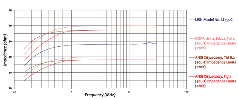
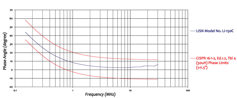
- ▸ Fully compliant with CISPR 16-1-2 and ANSI C63.4 — the 50 Ω / 50 µH V-network is calibrated to both standards, accepted by accredited EMC test laboratories worldwide.
- ▸ 50 A AC / 35 A DC current rating, 270 VAC / 380 VDC voltage rating — covers industrial control equipment, large office machinery, EV chargers, HVAC systems, commercial kitchen appliances, and medium-power motor drives.
- ▸ 50 µH air-core inductors prevent saturation — air-core construction keeps inductance constant at all currents up to 50 A, ensuring the defined LISN impedance remains stable and measurements stay calibrated.
- ▸ Superior Electric SUPERCON® shrouded sockets — safe shrouded design guards against accidental contact with live conductors at high currents; matching color-coded plugs included for mains and EUT wiring.
- ▸ 50 Ω N-type female RF connector — standard interface for direct connection to EMI receivers and spectrum analyzers; insertion loss < 0.5 dB and isolation > 40 dB across 150 kHz to 30 MHz.
- ▸ External transient limiter recommended — pair with the Com-Power LIT-153A or similar for impedance matching, out-of-band filtering, and EMI receiver input protection from the larger transients typical of higher-power EUTs.
- ▸ Unpainted mounting plate for low-impedance ground bond — metal-to-metal bonding to the test setup ground plane is essential for valid measurements at high currents and personnel safety.
- ▸ 3-phase ready — a second LI-150C pair extends the setup to 3-phase Wye or Delta power systems for testing 3-phase industrial and commercial equipment.
- ▸ Individually NIST-traceable calibrated — impedance, phase, isolation, and insertion loss data shipped with each unit. ISO 17025 accredited calibration available on request.
- ▸ Three-year standard warranty — backed by manufacturer support.
Specifications
| Model | LI-150C |
|---|---|
| Series | 1x Series — Single-conductor pair, separately housed |
| Specification | CISPR 16-1-2 / ANSI C63.4 |
| Application | Power Line conducted emissions tests |
| Frequency Range | 150 kHz – 30 MHz |
| Inductors | 50 µH (air-core) |
| Current Rating | 50 Amperes AC, 35 Amperes DC |
| Voltage Rating | 270 VAC (Line to Ground), 380 VDC |
| RF Connector | 50 Ohms N-type (female) |
| Insertion Loss | < 0.5 dB (150 kHz – 30 MHz) |
| Isolation | > 40 dB (150 kHz – 30 MHz) |
| Mains & EUT Connections | Superior Electric SUPERCON® shrouded sockets |
| Dimensions (each network) | 15 × 10 × 10 in (38 × 25.4 × 25.4 cm) |
| Weight (each network) | 14 lbs (6.3 kg) |
| Calibration | Individual, NIST-traceable; ISO 17025 accredited available on request |
| Warranty | Three-year standard warranty |
All values are typical, unless specified. Ships as a pair of separately housed networks. All specifications subject to change without notice.
🔍 Not Sure This Is The Right LISN?
Compare all 25 Com-Power LISN models side-by-side with our interactive selection tool. Filter by current, voltage, frequency, and standards to find your perfect match.
Compare All LISN Models →LI-150C CISPR 16-1-2 / ANSI C63.4 Single-Phase LISN FAQs
What is the LI-150C and what type of testing is it designed for?
The LI-150C is a single-conductor, 50Ω, 50 μH Line Impedance Stabilization Network (LISN) designed for power-line conducted emissions compliance testing per CISPR 16-1-2 and ANSI C63.4 at currents up to 50 A AC. It provides a defined, stable impedance on the power line, isolates the EUT from power source influences, and couples disturbance voltages to the RF measurement port. The LI-150C covers higher-power commercial and industrial products including large UPS systems, industrial motor drives, commercial HVAC equipment, and EV charging systems that exceed the 25 A rating of the LI-125C.
What standards does the LI-150C comply with and what do those standards require?
The LI-150C is fully compliant with CISPR 16-1-2 (specifying LISN electrical characteristics for conducted emissions measurements) and ANSI C63.4 (the American National Standard for radio-noise emissions measurement for FCC compliance). Compliance with both means the LI-150C is accepted by accredited EMC test laboratories worldwide for commercial product certification.
What is the frequency range of the LI-150C and why does conducted emissions testing start at 150 kHz?
The LI-150C covers 150 kHz to 30 MHz. Commercial conducted emissions testing begins at 150 kHz — the lower boundary defined by CISPR 16-1-2 and ANSI C63.4 for the standard 50 μH V-network LISN. The 30 MHz upper limit marks the boundary above which emissions are characterized as radiated. All products with power line connections must demonstrate compliance across the full 150 kHz to 30 MHz range.
What is the current rating of the LI-150C and what class of products does it support?
The LI-150C is rated at 50 A AC and 35 A DC. This supports large server systems, data center power distribution units, high-power UPS systems up to approximately 12 kW on a 240 V supply, industrial motor drives and variable frequency drives, commercial HVAC compressors, commercial kitchen equipment, welding power supplies, high-power EV battery chargers, large LED lighting systems, and power conversion equipment that would exceed the 25 A LI-125C rating.
What is the voltage rating of the LI-150C and what power systems does it support?
The LI-150C is rated at 270 VAC line-to-ground at 50–60 Hz and 380 VDC. This covers 120 V single-phase (North America), 230–240 V single-phase (Europe, Asia-Pacific), and DC supplies up to 380 V including 48 VDC telecom systems, 380 VDC data center DC distribution, and industrial DC bus configurations.
How does the LI-150C achieve its defined impedance and why is a 50 μH air-core inductor used?
A 50 μH inductor in series with the power line conductor, combined with a capacitor and resistor network, creates the defined 50 Ω termination at the RF port. Air-core inductors are essential at 50 A — any ferromagnetic core would saturate, causing inductance to collapse below 50 μH and invalidating the LISN impedance characteristic. Air-core inductors maintain a constant 50 μH at all currents up to the 50 A rating.
The LI-150C is sold as a pair of networks. Why is a pair required and how are they connected?
A single-phase AC system has two current-carrying conductors (Line and Neutral), and compliance testing requires a LISN in series with each conductor simultaneously. One unit is installed in the Line conductor and one in the Neutral. The measurement is performed one conductor at a time; the inactive RF port is terminated at 50 Ω. For three-phase systems, a second LI-150C pair accommodates the additional phase conductors.
What type of connectors does the LI-150C use at the mains and EUT ports?
The LI-150C uses Superior Electric SUPERCON® shrouded sockets at both mains and EUT ports. At 50 A, the shrouded design is especially important as accidental contact with live conductors at this current level presents a severe electrical hazard. Color-coded plugs for mains and EUT wiring are included, rated for the full 50 A current capacity.
Why is the mounting plate of the LI-150C left unpainted and what grounding is required?
The unpainted mounting plate enables a low-impedance metal-to-metal bond to the test setup ground plane. At 50 A operating currents, leakage currents through internal LISN capacitors are elevated and must have a defined return path to earth ground. Without a solid earth bond, these leakage currents create measurement errors and significant safety hazards.
What RF connector does the LI-150C use and what should be connected to the RF measurement port?
The LI-150C uses a 50 Ω N-type female RF connector, connecting via 50 Ω coaxial cable to an EMI receiver or spectrum analyzer. The inactive LISN RF port must be terminated with 50 Ω to maintain the correct impedance on the non-measured conductor. Com-Power recommends a Transient Limiter between the RF port and instrument, especially important with high-power EUTs that generate larger transients.
What insertion loss and isolation does the LI-150C provide and why do these parameters matter?
The LI-150C provides insertion loss below 0.5 dB and isolation above 40 dB across 150 kHz to 30 MHz. Low insertion loss ensures measured disturbance voltages accurately represent actual EUT emissions. High isolation prevents external facility power line noise from contaminating EUT emissions measurements at the RF measurement port.
How is the LI-150C individually calibrated and what calibration data is supplied?
Every LI-150C is individually calibrated per CISPR 16-1-2 and ANSI C63.4. Impedance, phase, isolation, and insertion loss data for the specific unit are supplied along with a certificate of calibration. Individual calibration enables precise insertion loss corrections during compliance testing, accounting for unit-to-unit component variations between nominally identical LISNs.
What is the warranty coverage for the LI-150C?
The LI-150C carries a three-year warranty from Com-Power Corporation. As a passive instrument without active components subject to wear, its service life is long under normal laboratory conditions. Periodic recalibration on a one- or two-year interval is recommended to maintain measurement traceability.
What are the physical dimensions and weight of the LI-150C?
Each LI-150C network measures 15 x 10 x 10 inches (38 x 25.4 x 25.4 cm) and weighs 14 lbs (6.3 kg). The LI-150C is larger and heavier than the LI-125C due to the larger air-core inductors required for 50 A operation. A complete single-phase installation requires substantial bench or floor space for both units on the ground plane, with high-current wiring rated for 50 A connecting the mains input and EUT output ports.
What is a Transient Limiter and why does Com-Power recommend one with the LI-150C?
A Transient Limiter is inserted between the LISN RF port and the EMI receiver. High-power EUTs such as motor drives, UPS systems, and large power supplies generate larger voltage transients than lower-power equipment, increasing receiver damage risk. The Transient Limiter provides impedance matching, attenuates out-of-band emissions below 150 kHz and above 30 MHz, and clamps transient voltages before they reach the receiver front end.
How does the LI-150C compare to the LI-125C, LI-1100C, and other Com-Power CISPR 16-1-2 / ANSI C63.4 LISNs?
The LI-125C (25 A AC), LI-150C (50 A AC), and LI-1100C (100 A AC, forced-air cooling) form the single-conductor CISPR 16-1-2 / ANSI C63.4 range, all sharing 150 kHz to 30 MHz, 50 Ω N-type RF, 50 μH air-core inductors, and individual calibration. The LI-150C fills the mid-range position. The LI-220C and LIN-120C are dual-conductor models limited to 20 A but more compact for lower-power products with a universal EUT receptacle.
What types of equipment cannot be tested with the LI-150C?
The LI-150C is not suitable for: equipment exceeding 50 A AC or 35 A DC (use LI-1100C at 100 A); equipment requiring DO-160 testing (use LI-325C or LI-350); equipment requiring MIL-STD-461 testing (use LI-400C or LI-4100); automotive CISPR 25 testing (use LI-550C); or three-phase equipment without a second pair (use two LI-150C pairs or a LI-3P series LISN).
How is the LI-150C used when performing conducted emissions compliance testing on a large UPS system?
Large UPS systems for server rooms and data centers can draw up to 50 A from the AC mains while charging internal batteries and supplying output power simultaneously. For EN 55032 or FCC Part 15 compliance, the LI-150C pair is installed between the AC mains and the UPS input, operated in normal AC-pass-through mode at rated input current with a representative load. CE measurements are taken on both Line and Neutral from 150 kHz to 30 MHz. The LI-150C’s 50 A rating allows full-load testing without derating, ensuring the worst-case emissions profile is correctly captured.
What does a typical setup look like when using the LI-150C for conducted emissions testing of a high-power EV battery charger?
Level 2 EV charging stations can draw up to 40–48 A from a 240 V single-phase supply at peak charging. The LI-150C pair is placed between a regulated 240 V AC source and the charger input, with the charger output connected to a battery simulator or resistive load. Conducted emissions are measured from 150 kHz to 30 MHz on both Line and Neutral at maximum rated input current. The LI-150C’s 50 A AC rating accommodates the full charging current without thermal derating, and its calibration data provides the insertion loss correction for compliance-ready results.
How is the LI-150C applied during conducted emissions testing of a commercial HVAC variable frequency drive?
Commercial HVAC VFDs commonly draw between 20 A and 50 A from single-phase 240 V supplies. During EN 55011 or EN 55032 conducted emissions testing, the LI-150C pair connects between the facility supply and the VFD input, with the VFD driving the motor at representative load. CE measurements are performed at several operating frequencies and load points to identify worst-case emissions, since VFD output frequency affects the switching pattern and harmonic content of the input current. The LI-150C’s stable 50 μH air-core inductors maintain accurate impedance throughout 150 kHz to 30 MHz regardless of the distorted current drawn by the VFD input rectifier.
How does an EMC test laboratory use the LI-150C for third-party compliance testing of industrial power supply products?
An accredited EMC laboratory receiving a high-power industrial power supply for CISPR 32 or EN 55032 conducted emissions testing first confirms the rated input current to determine whether the LI-125C or LI-150C is appropriate. For supplies up to 50 A, the LI-150C pair is set up on the calibrated ground plane. A calibrated electronic load at the power supply output achieves rated input current during the CE scan. Line and Neutral measurements from 150 kHz to 30 MHz are recorded with a CISPR quasi-peak and average detector. The LI-150C’s individual calibration insertion loss correction is applied to raw measurements, and results are compared against EN 55032 Class A or Class B limits. Both the laboratory’s accreditation status and the LI-150C’s calibration certificate are cited in the formal test report.
In what DC power system applications is the LI-150C used and how does the DC configuration differ from AC?
The LI-150C’s 380 VDC / 35 A DC rating supports conducted emissions testing of high-current 48 VDC telecom and data center power systems, 380 VDC industrial DC bus systems, DC-powered industrial machinery, and battery-fed DC drives. One LI-150C is installed in series with the positive DC bus conductor and one in the negative DC bus conductor. The air-core inductors carry DC current at rated levels without saturation, and the 150 kHz to 30 MHz impedance characteristic is identical to AC configurations, making the measurement method the same for both supply types.


Quote Request
Other EMC Test Equipment
- Absorbing Clamps
- Antenna Kits
- Antenna Masts - Automated and Manual
- Antennas
- Bulk Current Injection probes
- CDNs - Coupling Decoupling Network
- Comb Generators
- Conducted Immunity Test Systems
- Current Monitor Probes
- Current Probe Calibration Fixtures
- EM Clamps
- Feed Through Capacitor
- ISNs - Impedance Stabilization Network
- LISNs - Single Phase
- LISNs - TEMPEST
- LISNs - Three Phase
- Magnetic Field Generator
- Near Field Probes
- Power Amplifiers
- Pre-compliance Emissions Test Systems
- Preamplifiers
- Spectrum Analyzers
- Surge Generators
- System Controllers
- Transient Limiters
- Tripods For EMC
- Turntables