
AH-640 Standard Gain Horn Antenna
-
The AH-640 operates over a frequency range of 26.5 GHz to 40 GHz for both emission and immunity testing.
-
It can be used as both a receiving and transmitting antenna, making it versatile for various applications.
-
Each antenna is individually calibrated according to ANSI C63.5, with NIST traceability, and includes a calibration certificate.
-
The antenna is constructed from high-grade, corrosion-resistant aluminum, ensuring durability for both indoor and outdoor use.
-
It is capable of handling up to 10 Watts with a waveguide-to-coaxial adapter, and up to 200 Watts without, achieving high field strengths.
-
The AH-640 is commonly used for EMI compliance testing, radiated RF immunity tests, and measuring Effective Radiated Power (ERP) and Effective Isotropic Radiated Power (EIRP).
-
The antenna is easy to mount on any tripod or mast via its standard 1/4-inch x 20 mounting hole located in the center of its base plate.
-
It comes with a three-year standard warranty, ensuring long-term reliability and support.
Features
- ▸ Full Ka-band 26.5 GHz to 40 GHz coverage in a single horn — one antenna covers 5G FR2 n260 (39 GHz), 28 GHz 5G n257 upper portion, Ka-band satellite uplink/downlink, and the second-harmonic region of 77 GHz automotive radar.
- ▸ Standard gain horn design with high stable gain (avg 22.6 dBi) — precisely engineered Ka-band geometry produces predictable, repeatable gain across the band, ideal for substitution-method ERP/EIRP measurements at mmWave.
- ▸ Up to 200 W direct waveguide / 10 W coaxial — 200 W direct to the WR-28 waveguide flange supports radiated immunity at field strengths exceeding 1,000 V/m at 1 m; 10 W coaxial mode through the included waveguide-to-coax adapter for emissions and lower-power immunity.
- ▸ Removable waveguide-to-coax adapter — switch between coaxial drive (everyday instrumentation) and direct WR-28 waveguide drive (high-power immunity, lowest insertion loss) to match the application.
- ▸ 2.92 mm (K-type) coaxial connector — precision RF interface rated to 40 GHz, matching the antenna's full upper frequency. SMA-compatible mechanically but designed for the full Ka-band where standard SMA fails.
- ▸ Excellent VSWR (1.17–1.94, average 1.58:1) — tight match across the Ka-band protects high-power amplifiers and minimizes measurement uncertainty.
- ▸ Lightest passive horn in the lineup — just 1 lb (0.5 kg) and 5.9″ × 8.7″ × 9.3″ complete assembly, easy to reposition during multi-frequency 5G mmWave test campaigns.
- ▸ Standard 1/4″-20 mounting hole — located in the center of the antenna's base plate, mounts on the AT-812 Tripod or any compatible support.
- ▸ High-grade corrosion-resistant aluminum, painted finish — built for daily indoor and outdoor laboratory use, including continuous extreme weather exposure.
- ▸ Transmit and receive capable — serves both as a Ka-band emissions receive antenna and as a transmitting antenna for radiated immunity, eliminating antenna swaps between phases.
- ▸ ERP / EIRP substitution antenna — calibrated standard gain makes the AH-640 a preferred reference for Ka-band substitution measurements per FCC/TCB and ETSI procedures.
- ▸ Regulatory compliance applications — suitable for FCC Part 15/30, CE, MIL-STD-461 RE103/RS103, RTCA DO-160 Section 21, ETSI EN 303/EN 301 489, 3GPP TS 38.101-2, and CISPR 32.
- ▸ Individually calibrated, NIST-traceable — calibrated per ANSI C63.5; calibration certificate and antenna factor data ship with each unit; ISO 17025 accredited calibration available on request.
- ▸ Three-year standard warranty — backed by manufacturer support.
Specifications
| Product Name | Standard Gain Horn Antenna |
|---|---|
| Frequency Range | 26.5 GHz to 40 GHz |
| Polarization | Linear |
| Nominal Impedance | 50 Ω |
| Power Handling (CW) | 10 W with waveguide-to-coax adapter; 200 W direct waveguide |
| Connector | 2.92 mm (K-type, female) |
| Waveguide Flange | WR-28 |
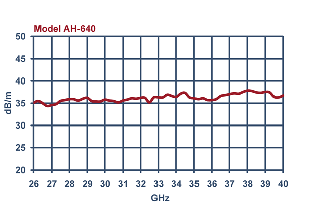
| Antenna Factor | 36.8 to 39.6 dB(m-1) [average: 37.9] |
| Isotropic Gain | 21.6 to 23.1 dBi [average: 22.6] |
| VSWR | 1.17 to 1.94 : 1 [average: 1.58] |
| Return Loss | 9.9 to 22 dB [average: 13.7] |
| Maximum Field Strength | >1,000 V/m at 1 m (with 200 W direct waveguide) |
| Radiated Field Strength | See typical field strength graph (10 W and 200 W input) |
| -3 dB Beamwidth | See typical beamwidth graph (E-plane and H-plane) |
| Applicable Standards | FCC, CISPR, EN, ETSI, FAA, MIL-STD-461, RTCA DO-160, SAE |
| Calibration | Individually calibrated per ANSI C63.5, NIST traceable |
| Mounting | 1/4″-20 threaded hole (center of base plate) |
| Horn / Waveguide Dimensions | 2.4″ × 3.1″ × 6.6″ [6.1 × 7.9 × 16.8 cm] |
| Complete Assembly Dimensions | 5.9″ × 8.7″ × 9.3″ [15 × 22 × 23.5 cm] |
| Weight | 1 lb [0.5 kg] |
All values are typical, unless specified. All specifications are subject to change without notice.
🔍 Not Sure Which Antenna You Need?
Compare all Com-Power antenna models side-by-side with our interactive selection tool. Filter by frequency range, antenna category, application, polarization, and power handling to find your perfect match.
Compare All Antenna Models →AH-640 Standard Gain Double Ridge Horn Antenna — Frequently Asked Questions
1. What is the Com-Power AH-640 and what is it primarily used for?
The AH-640 is a broadband standard gain double ridge waveguide horn antenna covering 26.5 GHz to 40 GHz — the full Ka-band millimeter-wave range. It is designed for EMC emissions and immunity testing, effective radiated power (ERP) and effective isotropic radiated power (EIRP) measurements, and antenna gain pattern characterization. As a linearly polarized transmit/receive antenna with at least 23 dBi gain across the band, it is well-suited for 5G mmWave, Ka-band satellite, automotive radar harmonic characterization, and mmWave research.
2. What are the AH-640’s key electrical and mechanical specifications?
Frequency: 26.5 GHz – 40 GHz (WR-28 waveguide band). Gain: ≥ 23 dBi across the entire band. Power handling: 5 W CW at the coaxial terminals, up to 10 W with the included waveguide-to-coax adapter, or up to 200 W direct to the waveguide flange. VSWR: < 2:1 typical. Polarization: linear. Connector: 2.92 mm (K-type), compatible with SMA. Impedance: 50 Ω. Construction: lightweight aluminum with corrosion-resistant finish for indoor/outdoor use. Size: 8.7″ × 5.7″ × 9″ max. Weight: 1.5 lbs (0.7 kg). Mounting: ¼″-20 threaded hole on oval rear plate. Calibration: individual per ANSI C63.5 with NIST traceability; ISO 17025 available.
3. Why are millimeter-wave horn antennas like the AH-640 needed for modern EMC testing?
EMC test standards have steadily extended their upper frequency limits to follow modern wireless spectrum allocation. CISPR 32 radiated emissions now extend to 6 GHz (Class B) and up to the highest internal clock frequency for ITE. MIL-STD-461G RE103 can require coverage to 40 GHz. Automotive standards now cover 77 GHz radar harmonics. 5G NR FR2 uses bands at 24, 28, 37, 39, and 47 GHz. Satellite systems operate in the Ka-band (26.5–40 GHz). Without a dedicated mmWave antenna such as the AH-640, conducted-only or sub-6-GHz setups miss emissions or susceptibility issues at these frequencies — and compliance reports cannot cover the full required range.
4. Which EMC standards and applications use the AH-640’s frequency range?
• FCC Part 15 Subpart E (U-NII devices, intentional radiators in mmWave bands)
• FCC Part 30 (Upper Microwave Flexible Use Service, 28/37/39 GHz)
• CISPR 32 / EN 55032 (ITE/multimedia emissions to highest clock × 5)
• CISPR 16-1-4 (site validation and SVSWR above 1 GHz)
• MIL-STD-461G RE103 and RS103 (military EMI/EMS to 40 GHz)
• RTCA DO-160 Section 21 (airborne equipment emissions, mmWave variants)
• ETSI EN 303 645 / EN 301 489 (European wireless compliance)
• 3GPP TS 38.101-2 (5G NR FR2 radio performance)
• ISO 11452-2 (automotive radar harmonic coverage above 26.5 GHz)
5. What real-world products and systems use AH-640 testing?
• 5G NR FR2 equipment: 28 GHz (n257, n261) and 39 GHz (n260) base stations, customer-premises equipment, handsets, small cells
• Ka-band satellite: LEO/GEO user terminals, VSAT, gateway radios, satellite backhaul, earth-station verification
• Automotive radar: harmonic content from 24 GHz short-range and 77 GHz long-range radars (second and third harmonics fall into Ka-band)
• Point-to-point microwave links: 28 GHz and 38 GHz backhaul radios, E-band precursors
• Aerospace/defense: Ka-band SATCOM terminals, military radars, electronic warfare receivers, missile seekers
• Research and test: 5G lab testbeds, antenna pattern measurement ranges, component-level EIRP verification
• Security/surveillance: millimeter-wave body scanners and imaging systems
6. What is “standard gain” and how does it differ from a broadband high-gain horn?
A standard gain horn (SGH) is a pyramidal or conical horn designed to a precisely known theoretical gain that tracks smoothly across its waveguide band. The AH-640’s ≥ 23 dBi gain is both high and stable across frequency, which makes it ideal as a substitution antenna for ERP/EIRP measurements — you compare the unknown device’s emission against the calibrated horn’s response at the same frequency and location to derive absolute radiated power. Broadband ultra-wide horns (like the AH-118, 1–18 GHz) cover more spectrum but with lower and more variable gain. For Ka-band work where you need predictable, high-gain behavior, a standard gain design such as the AH-640 is preferred.
7. Why does the AH-640 come with a waveguide-to-coax adapter, and when should I bypass it?
At mmWave frequencies, the native transmission line for low loss is rectangular waveguide — for the 26.5–40 GHz band that is WR-28. The AH-640 is physically a WR-28 horn, but the included precision waveguide-to-coaxial adapter with a 2.92 mm (K-type) connector lets you drive it with everyday coaxial amplifiers, spectrum analyzers, and signal sources. Use the coax adapter for emissions receive (high dynamic range, easy instrument interfacing) and for immunity transmit up to 10 W. Remove the adapter and feed the waveguide flange directly when you need the full 200 W CW rating or when your amplifier already has a WR-28 output — direct waveguide coupling also lowers loss, giving cleaner reference data.
8. How does the AH-640 compare with other Com-Power horn antennas?
• vs. AH-118 (700 MHz–18 GHz, 300 W): AH-118 is the workhorse for sub-18 GHz; AH-640 extends coverage into Ka-band where AH-118 stops
• vs. AH-826 (18–26.5 GHz): AH-826 fills the K-band gap; AH-640 covers the next band up. Own both for full 18–40 GHz coverage as two separate antennas
• vs. AH-840 (18–40 GHz): AH-840 combines 826 + 640 ranges into one antenna. AH-640 alone is the lower-cost choice if you only need 26.5–40 GHz and not the 18–26.5 GHz band
• vs. AH-8055 (800 MHz–5 GHz): fundamentally different frequency class; no overlap. A complete sub-6 + Ka-band lab typically pairs AH-8055 with AH-640
9. Should I choose the AH-640 or the AH-840?
Choose AH-640 when your testing is concentrated in the 26.5–40 GHz band — 28 GHz and 39 GHz 5G, satellite Ka-band, 77 GHz automotive radar harmonics, Ka-band EIRP measurements. It is lighter (1.5 lbs vs. 1 lb for the AH-840 horn), less expensive than the combined-band AH-840, and offers higher gain (≥23 dBi vs. typical 15–25 dBi on the AH-840). Choose AH-840 if you also need the 18–26.5 GHz (K-band) range — for 24 GHz automotive radar, 5G FR2 n257/n258 bands, or consolidating to one antenna for full 5G FR2 coverage without swapping between tests.
10. How much amplifier power do I need to hit common field strengths with the AH-640?
Using E ≈ √(30·P·G) / d at 1 m and 23 dBi gain:
• 10 V/m: ~0.02 W — 1 W amp is plenty
• 30 V/m: ~0.15 W
• 100 V/m: ~1.7 W — 10 W amp with margin
• 200 V/m: ~6.7 W — 25–50 W amp
• 500 V/m: ~42 W — requires direct waveguide drive
• ~1,100 V/m: ~200 W (direct waveguide ceiling)
Stay within the 5 W coax / 10 W adapter / 200 W waveguide limits. Add 3–6 dB headroom for VSWR, cable loss, and modulation crest factor. Cable loss at Ka-band is significant — use short, low-loss coax assemblies or stay on waveguide near the amplifier to preserve forward power.
11. What is the 2.92 mm K-type connector and why is it used at 40 GHz?
The 2.92 mm connector (also called K-type) is a precision RF coaxial interface rated to 40 GHz — above the usable limit of the common SMA connector (18 GHz, sometimes pushed to 24 GHz with precision SMA). It is mechanically compatible with SMA, meaning a 2.92 mm plug will mate with an SMA jack and vice versa, but only a 2.92 mm-to-2.92 mm mating achieves the full 40 GHz performance. For the AH-640 you want 2.92 mm on both sides of every coaxial joint: at the antenna, at the cable, and at the amplifier/receiver — otherwise connector VSWR rises sharply above 18 GHz.
12. What cable and setup considerations matter most at 26.5–40 GHz?
• Cable loss dominates — typical low-loss coax assemblies lose 0.5–1.5 dB per foot at 40 GHz. Keep coax runs under 1 m whenever possible; use phase-stable precision microwave cable
• Connector torque matters — always torque 2.92 mm connectors to manufacturer spec (typically 8 in-lb) using a calibrated wrench
• Inspect before every mate — mmWave connectors are unforgiving; dust or damaged pins destroy measurements
• Waveguide alignment — if using WR-28 flanges direct, align flange pins and torque evenly to avoid flange leakage
• Distance — at mmWave, far-field starts at < 30 cm for most EUTs; 1 m is typically sufficient test distance
• Absorber quality — ensure chamber absorbers are rated for 40 GHz; legacy absorbers may underperform above 18 GHz
13. Why is calibration especially critical at mmWave frequencies, and what does NIST-traceable mean?
At Ka-band, small mechanical variations (flange flatness, connector wear, waveguide bends) produce larger effects than at lower frequencies. Without proper calibration, a 40 GHz emissions reading can easily be 3–5 dB off. Com-Power calibrates every AH-640 individually per ANSI C63.5 with NIST traceability — a documented chain of comparisons back to the U.S. National Institute of Standards and Technology primary standards. The calibration data gives antenna factor (or gain) vs. frequency, which your receiver applies automatically to correct the reading. ISO 17025 accredited calibration is available on request when your accreditation body requires an externally audited certificate. Recalibrate annually for maintained traceability.
14. Beyond EMC, what other applications does the AH-640 serve?
• Antenna gain pattern measurement — rotate an antenna-under-test (AUT) in an anechoic range while the AH-640 receives the swept signal to produce E/H-plane radiation patterns
• EIRP and ERP measurement — use the AH-640 as the reference antenna in a substitution method to derive absolute radiated power of a transmitter
• Site characterization — mmWave chamber validation, reflection coefficient measurement, SVSWR at 26.5–40 GHz
• Surveillance / signal intelligence — directional reception of K/Ka-band emissions for detection and classification
• 5G component test — over-the-air (OTA) verification of phased-array modules, RFIC test, packaged antenna testing
• Radar harmonic / spurious measurement — sensing 77 GHz radar second harmonics (fundamental aliasing into 39 GHz regions) and other radar spurs
15. What are the AH-640’s key design advantages?
• Full 26.5–40 GHz coverage in a single broadband horn — no antenna swap across the band
• High, stable gain (≥23 dBi) — the best-case gain spec among Com-Power’s mmWave horns
• Two drive options: 5 W (coax), 10 W (with adapter), or 200 W (direct waveguide) — flexibility for both emissions and high-field immunity
• Lightweight and compact: 1.5 lbs (0.7 kg), 8.7 × 5.7 × 9 in — easy to position and mount
• Precision 2.92 mm (K-type) connector — proper mmWave interface rated to 40 GHz
• Standard ¼″-20 mount — works with every common tripod or mast
• Corrosion-resistant aluminum — daily lab use or occasional outdoor site work
• Individual NIST-traceable calibration included; ISO 17025 available
• Both transmit and receive capable — one antenna for emissions and immunity in the same band
16. When should engineers select the AH-640 over other Com-Power antennas?
Select the AH-640 when any of the following applies:
• Your tests include 5G NR FR2 bands at 28 GHz (n257, n261), 37 GHz (n260), or 39 GHz
• You need Ka-band satellite coverage for ground-terminal or user-equipment verification
• You are measuring 77 GHz automotive radar harmonics or Ka-band radar emissions
• Your standard is MIL-STD-461G, DO-160, FCC Part 15 Subpart E, or CISPR 32 with a 40-GHz upper limit
• You need EIRP/ERP substitution measurements at mmWave and want a high-gain, stable reference antenna
• Your antenna pattern or research work requires 26.5–40 GHz coverage in one broadband unit
Choose the AH-840 instead if you also need 18–26.5 GHz in the same antenna. Choose the AH-826 if your testing is limited to 18–26.5 GHz (24 GHz automotive, 5G n257/n258). Choose the AH-118 for 1–18 GHz coverage, or the AH-8055 for high-field 800 MHz–5 GHz immunity.
Application Notes (PDF)
- AN-107 — What is Antenna Factor?
- AN-106 — Use of Antenna Factor for EMC Measurements
- Selecting the Right EMI Antenna
- Considerations when Selecting an Antenna for RF Immunity Testing
- EMC Antenna Calibration Requirements, Methodologies, and Best Practices
- NIST Antenna Calibration Services — Com-Power Capabilities and Traceability
- Com-Power EMC Antenna Product Line — Complete Specifications
- Accounting for Ambient Noise
Interactive Tools
- Antenna Finder Wizard
- Com-Power Antenna & Field Strength Calculator
- Com-Power EMC Compliance Limits Calculator
- Com-Power Cable Loss & Attenuation Calculator
- Com-Power VSWR / Return Loss / Mismatch Loss Calculator
- Com-Power Free Space Path Loss & Link Budget Calculator
Industry Applications
- EMC Considerations for IoT and Smart Home Devices
- Automotive EMC Testing — ISO 11452 / CISPR 25
- 5G Equipment EMC Testing — New Challenges in EMC Compliance
- Medical Device EMC Compliance — IEC 60601-1-2 Essentials
- EV Charging Systems — EMC Requirements and Compliance
Blog Articles


Quote Request
Other EMC Test Equipment
- Absorbing Clamps
- Antenna Kits
- Antenna Masts - Automated and Manual
- Antennas
- Bulk Current Injection probes
- CDNs - Coupling Decoupling Network
- Comb Generators
- Conducted Immunity Test Systems
- Current Monitor Probes
- Current Probe Calibration Fixtures
- EM Clamps
- Feed Through Capacitor
- ISNs - Impedance Stabilization Network
- LISNs - Single Phase
- LISNs - TEMPEST
- LISNs - Three Phase
- Magnetic Field Generator
- Near Field Probes
- Power Amplifiers
- Pre-compliance Emissions Test Systems
- Preamplifiers
- Spectrum Analyzers
- Surge Generators
- System Controllers
- Transient Limiters
- Tripods For EMC
- Turntables